2-10
Functional Description
Information on the Resistive Heating Element's Activation Circuitry
The resistive heat elements are divided into four groups. Two groups have 12
elements, the other two groups have 13. Only one element can be activated at
each time in each group, and therefore no more than four elements can be
activated simultaneously.
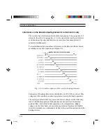
To avoid induction between adjacent elements, each element will be activated
according to a specific sequence (see figure 2-4).
Fig. 2-4: Activation sequence of the resistive heating elements
Each group of heating elements is controlled by an 18.8 V driver circuit. This
voltage must be regulated in order to guarantee correct print head operation.
The most typical faults that may occur with lower voltages are the following:
lack of ink bubble expulsion if the print head is not used for a determined
period of time, lack of ink bubble expulsion in low temperatures. Higher
voltages, on the other hand, can cause the generation of incorrect ink bubble
control commands or no command at all due to the possible deterioration of the
heating element.
Resistive Element Activation Command
S-2.PM5
11/7/94, 13:40
10
Содержание DECcolorwriter 120ic
Страница 58: ...3 21 Installation Fig 3 21 Fonts selector switches settings S 3 PM5 11 7 94 17 16 21 ...
Страница 59: ...3 22 Installation Fig 3 22 Character sets selector switches settings S 3 PM5 11 7 94 17 16 22 ...
Страница 60: ...3 23 Installation Fig 3 23 Character sets selector switches settings S 3 PM5 11 7 94 17 16 23 ...
Страница 69: ...5 3 Diagnostics and Tests Fig 5 1 Example of monochrome print test page 1 S 5 PM5 11 7 94 17 18 3 ...
Страница 78: ...7 3 Electrical Interconnections Fig 7 1 Main board S 7 PM5 3 14 97 3 38 PM 3 ...


