background image

viii

Preface

Associated Documentation

EK-LJ12E-UG

DECcolorwriter 120ic Printer - User Guide

EK-LJ12E-RF

DECcolorwriter 120ic Printer - Setting Up Your Printer

EK-LJ11*-UG

DECwriter 110i Printer - User Guide

EK-LJ11*-RF

DECwriter 110i Printer - Setting Up Your Printer

The DECcolorwriter 120ic Printer documentation set is only available in
English.

The * in the above order numbers corresponds to the language identifier for the
appropriate language: A for American, E for English, F for French, G for
German, I for Italian, S for Spanish.

PREFACE.PM5

11/7/94, 17:41

8

Содержание DECcolorwriter 120ic

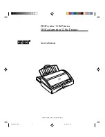
Страница 1: ...Order Number EK LJ12E SV 001 DECcolorwriter 120ic Printer DECwriter 110i Printer DECwriter 110i TM Service Manual COVERSV PM5 11 7 94 17 39 1 ...

Страница 2: ...y Digital Equipment Corporation Digital Equipment Corporation assumes no responsibility for any errors that may appear in this document Possession use or copying of the software described in this publication is authorized only pursuant to a valid written license from Digital or an authorized sublicensor Digital Equipment Corporation 1994 All rights reserved The following are trademarks of Digital ...

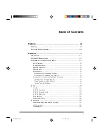
Страница 3: ...nts for Portrait Page Formats 1 7 List of Fonts for Landscape Page Formats 1 8 Optional Fonts Available with the Basic Emulation 1 8 Prestige Elite Card 256 Kbytes 1 8 Times Nordic Card 256 Kbytes 1 9 Nordic Card 256 Kbytes 1 9 Options 1 10 Color Kit 1 10 PCMCIA Font Cards 1 10 PCMCIA Emulation Card 1 10 PCMCIA RAM Card 1 10 Serial Interface 1 11 Parallel Data Cables 1 11 Accessories 1 11 Monochro...

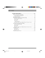
Страница 4: ...inting 2 7 Print Nozzles 2 9 Matrix components 2 9 Information on the Resistive Heating Element s Activation Circuitry 2 10 Color Ink Jet Print Head Functioning 2 11 Ink Jet Print Head Description 2 11 Ink Jet Printing 2 13 Print Nozzles 2 13 Information on the Resistive Heating Element s Activation Circuitry 2 14 Operating Controls 2 15 Operator Panel 2 15 Buttons Functions 2 16 Print Head Select...

Страница 5: ...12 Inserting a Memory Card 3 14 Installing the Serial Interface 3 15 Print Test 3 16 Connecting the Printer to the Computer 3 16 Centronics Parallel Interface 3 16 Powering off the Printer 3 17 Installation Setup 3 18 Factory Settings 3 18 Programmable Parameters 3 19 Programming the Parameters and Running Setup 3 19 First Group of Selectors 1 6 3 20 Second Group of Selectors A H 3 20 Third Group ...

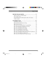
Страница 6: ... Color Print Head 4 5 Diagnostics and Tests 5 1 Power On Diagnostics 5 1 Monochrome Print Test 5 1 Color Print Test 5 4 Data Scop Printing Hex Dump 5 4 TroubleshootingGuide 5 5 Problems at Power On 5 5 Inacceptable Print Quality 5 5 Incorrect Paper Feed 5 6 Incorrect Data Transmission 5 6 States and Indicator Meanings 6 1 Operating States 6 1 Functional States 6 2 IndicatorMeanings 6 2 Indicator W...

Страница 7: ... Replacing the Print Head 8 3 Removing Remounting the Printer s Casing and Base 8 4 Removing Remounting the Mechanical Assembly 8 5 Removing Remounting the Main Board 8 6 Removing Remounting the Power Group 8 7 Removing Remounting the Operator Panel 8 8 Removing Remounting the Paper Feed Motor 8 9 Removing Remounting the Mechanical Assembly Front Structure 8 10 Removing Remounting the Carriage Mot...

Страница 8: ...lor kit including a color print head a print head storage box and the DECcolorwriter 120ic color printer driver and that the LJ 110 can be upgraded with the color kit In all other respects the two printers are identical and therefore all instructions described in this manual are applicable to both printers unless reference is made to a specificmodel The chapters are ordered in a way to develop an ...

Страница 9: ...er 110i Printer User Guide EK LJ11 RF DECwriter 110i Printer Setting Up Your Printer The DECcolorwriter 120ic Printer documentation set is only available in English The in the above order numbers corresponds to the language identifier for the appropriate language A for American E for English F for French G for German I for Italian S for Spanish PREFACE PM5 11 7 94 17 41 8 ...

Страница 10: ...a fast writing speed a low noise level and considerable versatility in the paper handling This non impact printer is designed and constructed to guarantee reliability and to give constant quality of both text and high resolution graphics It uses drop on demand thermal inkjet technology associated with very low power con sumption It produces a laser like print density of up to 300 dpi the mono chro...

Страница 11: ...y Print Matrix 300 x 300 dpi Print Definition Vertical x Horizontal 1 150 in x 1 300 in for Draft 1 300 in x 1 300 in for LQ Print Density 75 100 150 300 dpi Print Pitch 10 12 16 67 cpi PS Each basic fixed pitch value can be condensed to half and expanded to double its value e g 10 cpi 5 cpi 20 cpi Print Line Length Portrait orientation 80 characters with 10 cpi pitch 96 characters with 12 cpi 132...

Страница 12: ... Italic Portrait Landscape Letter Gothic Upright Italic Portrait Upright Landscape Book Face Times Upright Italic Portrait Times Nordic Upright Italic Portrait Linea Upright Italic Portrait Line Draw Fonts Cards One optional memory card at a time Paper Handling Automatic ASF tray capacity 70 x 21 lb sheets 80 g m2 Manual including thick documents film envelopes weight up to 135 g m2 Interface Resi...

Страница 13: ...ectromagnetic Compatibility FCC Class B Certified Safety Regulations USA UL 1950 478 Canada CSA C22 2 For power supply voltage 220 240 V Electromagnetic Compatibility EN 55022 Class B CEE 87 308 VDE 0871 level B DBP Verf 243 1991 Safety Regulations EN 60950 Nordic Deviations Germany GS EN 60950 9 88 e ZH 618 Physical Characteristics Printer ready for use Height 11 05 in 281 mm Width 14 21 in 361 m...

Страница 14: ... the relative character sets and both are stored on a specific card The optional emulations are capable of handling optional memory card fonts In order to enhance the graphic fonts of the LQ 850 and X 24 emulations a memory extension card that allows DLL Down Line Loading management needs to be installed Character Generator The character generator assigns a specific printable character to each cod...

Страница 15: ...w PC Slovenia PC Kamenicky Character Sets CP 437 International Roman 8 PC 8 Denmark Norway CP 850 Multilingual ECMA 94 Latin 1 ISO 4 United Kingdom ISO 21 Germany ISO 69 France ISO 15 Italy ISO 60 Norway 1 ISO 61 Norway 2 ISO 11 Sweden Names ISO 10 Sweden ISO 17 Spain ISO 6 ASCII ISO 2 IRV ISO 16 Portugal ISO 14 JIS ASCII Legal CP 860 Portugal Danish OPE I UNIX International Line Draw NOTE In the ...

Страница 16: ...33 34 Letter Gothic 6 12 5 10 20 Letter Gothic 6 12 6 12 24 Gothic italic 6 12 6 12 24 Letter Gothic 4 75 9 5 8 33 16 67 33 34 TMS Nordic 6 12 Proportional TMS Nordic italic 6 12 Proportional BF Times 7 14 Proportional BF Times italic 7 14 Proportional BF Times 6 12 Proportional BF Times italic 6 12 Proportional BF Times 5 10 Proportional BF Times italic 5 10 Proportional BF Times 4 8 Proportional...

Страница 17: ... Consist of a series of characters with the same ISO code as the basic character generator but with different fonts These fonts reside on optional cards whose contents are listed in the following tables Prestige Elite Card 256 Kbytes Fonts Height Pitch Page Format Setup N0 Prestige Elite 10 12 Portrait 101 Prestige Elite corsivo 10 12 Portrait 102 Prestige Elite 7 16 67 Portrait 103 Letter Gothic ...

Страница 18: ...trait 116 Times Nordic italic 10 Proportional Portrait 117 Times Nordic 8 Proportional Portrait 118 Times Nordic italic 8 Proportional Portrait 119 Font Height Pitch Page Format Setup N0 Nordic 30 Proportional Portrait 121 Nordic 14 Proportional Portrait 122 Nordic italic 14 Proportional Portrait 122 Nordic 12 Proportional Portrait 124 Nordic italic 12 Proportional Portrait 125 Nordic 10 Proportio...

Страница 19: ...with a booklet which illustrates the font card contents and explains the font selection procedure Font Card B Prestige Elite 7 10 pt 16 67 12 cpi LJ50X CH Letter Gothic 12 pt 12 cpi Line Draw Font Card R U Times Nordic 8 10 12 14 30 pt PS LJ50X CJ Font Card T V Nordic 8 10 12 14 30 pt PS LJ50X CK PCMCIA Emulation Card IBM Proprinter X24 EPSON LQ 850 multi emulation LJ11X IE PCMCIA RAM Card Other s...

Страница 20: ...ollows Set of 1 complete monochrome print head printing unit ink cartridge and 1 monochrome ink cartridge LJ50X AB Set of 2 monochrome ink cartridges 400 pages life each LJ50X AC Color Print Head The color print head consisting of a single unit including the printing unit and the ink cartridge not replaceable is available packaged as follows Set of 1 color print head 200 pages life LJ50X AK Transp...

Страница 21: ...onal Description 2 Functional Description This chapter describes the different functional and physical parts of the LJ 110 120 printer It also explains how an ink jet print head functions S 2 PM5 11 7 94 13 39 1 ...

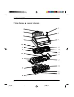
Страница 22: ...2 2 Functional Description Printer Components and Internals 6 12 20 21 22 17 13 2 3 4 11 1 5 7 16 10 9 8 15 14 19 18 S 2 PM5 11 7 94 13 39 2 ...

Страница 23: ...t cover 7 Operator panel 8 Paper feed stepper motor 9 Selectorswitches 10 Print head 11 Carriage reset and setup parameter read photosensor 12 Carriage transport stepper motor 13 Inkslide 14 Power group On Off switch power cord 115 220 240 V transformer 15 Paper detection photosensor 16 Optional memory card connector 17 Main board 18 Printer base and ASF support 19 Paper input tray 20 Paper insert...

Страница 24: ...24 Parallel Interface Centronics Power Group Transformer 115 220 240 V Fuse ON OFF Switch Print Group Memory Card Operator Panel Carriage Motor Carriage Reset and Setup Parameter Read Sensor Paper Feed Motor ASF Tray Manual Paper Feed NOTE The blocks with dashed lines are options S 2 PM5 11 7 94 13 39 4 ...

Страница 25: ...n figure 2 1b The ink is contained in a disposable cartridge mounted inside the shell hosting the nozzles The ink flows to the nozzles through small channels in the print head s resin layer This layer is electrically insulated from the resistive heating elements A sponge inside the cartridge prevents the ink from being shaken during print head movements This avoids problems during carriage transla...

Страница 26: ...g 140 150µ µ µ µ µm Flexible Electric Grid Heating Element Nozzle Pad Shell Ink Sponge Cover INKCARTRIDGE Nozzle Fig 2 1 Ink jet print head Fig 2 1b Nozzle cross section Fig 2 1c Exploded view of the print head Fig 2 1a Ink jet print head and ink cartridge S 2 PM5 11 7 94 13 39 6 ...

Страница 27: ...ink bubble As the ink bubble begins to expand it pushes the ink out of the nozzle and onto the paper This ink droplet is expelled from the nozzle at a rate of about 15 m sec Figure 2 2 a e shows the highlights of how an ink bubble is created and expelled from the nozzle When the resistive heating element is no longer energized and the ink droplet exits the nozzle new ink from the cartridge replace...

Страница 28: ...elled Fig 1 4d The ink bubble breaks and the ink is propelled onto the paper Fig 2 2c The ink bubble expands to its maximum size Fig 2 2b An electrical signal is applied to the heating element and an ink bubble is created The ink exits the nozzle Fig 2 2a Initial stage Fig 2 2 The creation of an ink droplet Ink S 2 PM5 11 7 94 13 39 8 ...

Страница 29: ... In each row the nozzles are sequentially placed on each column as shown in figure 2 3 Matrix components Dampering balancing nozzles A C and B D for the outermost 2 50 and 1 49 nozzles Ink cartridge balancing nozzles E and L GROUP A 12 GROUP B 13 GROUP D 12 GROUP C 13 Fig 2 3 Nozzle matrix S 2 PM5 11 7 94 13 40 9 ...

Страница 30: ...g 2 4 Activation sequence of the resistive heating elements Each group of heating elements is controlled by an 18 8 V driver circuit This voltage must be regulated in order to guarantee correct print head operation The most typical faults that may occur with lower voltages are the following lack of ink bubble expulsion if the print head is not used for a determined period of time lack of ink bubbl...

Страница 31: ... ink jet print head They are assembled on a nickel and gold compound referred to as being electroformatted and have a conical shape as shown in figure 2 5b The ink is contained in three cartridges one for each color A sponge inside each cartridge prevents the ink from being shaken during print head movements This avoids problems during carriage translations avoids the ink from leaking out of the b...

Страница 32: ...or ink jet print head Nozzle Heating Element Fig 2 4c Exploded view of the print head Ink Sponges Cover Ink Filter Outer Casing Flexible Electric Grid Heating Element Nozzle Pad INKCARTRIDGE Fig 2 5b Nozzle cross section Fig 2 5 Ink jet print head S 2 PM5 11 7 94 13 40 12 ...

Страница 33: ...total of 51 print nozzles are arranged on two vertical rows of 25 and 26 nozzles and are divided horizontally in three groups one for each color Figure 2 6 shows how the nozzles are placed on each row Yellow Magenta Blue 2 4 6 8 1 3 5 7 19 21 23 25 20 22 24 26 44 46 48 50 45 47 49 51 Fig 2 6 Nozzle matrix S 2 PM5 11 7 94 13 40 13 ...

Страница 34: ...7 Activation sequence of the resistive heating elements Each group of heating elements is controlled by an 18 8 V driver circuit This voltage must be regulated in order to guarantee correct print head operation The most typical faults that may occur with lower voltages are the following lack of ink bubble expulsion if the print head is not used for a determined period of time lack of ink bubble ex...

Страница 35: ...g 2 8 Operator panel The operator panel buttons allow you to install the print head expell the paper and switch the printer ON or OFF line The indicators signal machine status and out of paper or error conditions For more information about the indicator meanings see chapter 6 On Line Install Cartridge Form Feed On S 2 PM5 11 7 94 13 40 15 ...

Страница 36: ...pels the sheet of paper With the printer ON LINE and BUSY immediately prints the contents of the buffer and expels the printedsheet With the printer OFF line and loaded with paper expels the paper If the printer is out of paper allows you to manually load a sheet of paper to the first printable line Pressing this button while powering on the printer will automatically run a print test Upon complet...

Страница 37: ...ver away from the printer BLACK When installing a color print head move this lever towards the inside of the printer COLOR Fig 2 9 Print head selection lever NOTE Always make sure that the lever is positioned according to the type of print head installed The lever is not positioned correctly if the On Line indicator begins to flash twice followed by a single flash of the On indicator BLACK COLOR S...

Страница 38: ...the installation procedure see the LJ 110 120 Printer User Guides General Rules The following rules need to be followed to ensure optimum printer performance and to avoid making service calls for problems that do not directly involve the printer Line Voltage Supply The LJ 110 120 complies with the safety and electromagnetic interference EMI norms drawn up by the following commissions S 3 PM5 11 7 ...

Страница 39: ...ect to variations that are higher than those toler ated and with a greater degree of electromagnetic interference Always connect the printer to a grounded power outlet Locating the Printer The printer must be used on a flat steady surface Keep it away from ventila tors radiators and direct sunlight These instructions are particularly important for ink jet printers Environmental Conditions The envi...

Страница 40: ...e following components 1 LJ 110 120 printer 2 Print head storage box LJ 120 only or LJ 110 color kit 3 Monochrome print head 4 Color print head LJ 120 only or LJ 110 color kit 5 Setting Up Your Printer booklet 6 Printer User Guide 7 Paper output tray 8 Paper input tray 9 Printer driver diskettes number depending on the printer type S 3 PM5 11 7 94 17 14 3 ...

Страница 41: ...lity printing by indicating when the ink cartridge is nearly empty To install the print head Power on the printer Press the Install Cartridge button in order to move the print head to the print head installation replacement position Lift the printer s top cover Open the container in which the print head is stored A User Guide inside the container gives you the information needed for installing the...

Страница 42: ...ead on it Fig 3 3 Removing the protective tape Fig 3 4 Installing the print head Make sure the print head is installed correctly Try again if you are not sure Close the printer s top cover 2 1 With the electrical contacts facing the front of the printer insert the print head in its slot by pushing it downwards 1 then pull it towards the front of the printer until it clicks 2 S 3 PM5 11 7 94 17 14 ...

Страница 43: ...r part of this tray supplied with the printer The paper input tray can hold up to 70 x 21 lb 80 g m2 sheets of paper Insert the paper feed tray s mounting studs into the respective slots on the lower rear of the printer 1 Make sure that the power cord is threaded through the U shaped guide on the edge of the paper feed tray 2 Fig 3 5 Inserting the paper input tray 1 2 S 3 PM5 11 7 94 17 14 6 ...

Страница 44: ... This tray is positioned on the top rear of the printer Insert the tray s mounting studs into the respective slots on the top rear of the printer This tray can hold up to 30 x 21 lb 80 g m2 sheets of paper The center part of the tray can be extended outward so that the tray can hold longer forms Fig 3 6 Mounting the paper output tray S 3 PM5 11 7 94 17 14 7 ...

Страница 45: ...per The following table will aid you in determining the printable area for the two most common paper formats used A4 and Letter Legal The figure on the facing page shows the meaning of the listed values A4 Letter Legal mm inches mm inches M 210 0 8 26 215 9 8 5 W 203 2 8 0 203 2 8 0 L 3 4 0 134 6 4 0 25 R 3 4 0 134 6 4 0 25 T 1 0 0 04 1 0 0 04 B 15 24 0 6 15 24 0 6 S 3 PM5 11 7 94 17 14 8 ...

Страница 46: ... area 1 Printer mechanical path On the lower front of the printer there are two levers which control the centering and the securing of the paper in the paper tray B A Fig 3 8 A Paper securing lever B Paper centering lever S 3 PM5 11 7 94 17 15 9 ...

Страница 47: ... move towards the left Fig 3 9 Moving the levers to insert the paper To make paper loading easier extend the central part of the paper tray without removing it Leaf the pack of paper Place the paper in the tray and then push it towards the printer until touching the feed rollers inside the tray Fig 3 10 Loading the paper S 3 PM5 11 7 94 17 15 10 ...

Страница 48: ...11 Closing the paper tray Once paper is loaded in the tray move the lower level B to the left in order to close the lateral guides and center the paper in the tray Move lever A to the right and then upwards Fig 3 12 Moving the levers to secure the paper S 3 PM5 11 7 94 17 15 11 ...

Страница 49: ...will aid you in determining the printable area for the most commonly used envelope sizes C5 DL COM 10 and C6 C5 DL COM 10 mm inches mm inches mm inches M 229 0 9 02 220 0 8 66 241 3 9 5 W 203 2 8 0 203 2 8 0 203 2 8 0 L R T 1 0 0 04 1 0 0 04 1 0 0 04 B 15 24 0 6 15 24 0 6 15 24 0 6 M L R W T B 1 Fig 3 13 Print area 1 Printer mechanical path S 3 PM5 11 7 94 17 15 12 ...

Страница 50: ...ft hand side envelopes should be aligned against the right hand side of the support Push the paper into the paper feed slot until touching the feed rollers Press the Form Feed button Fig 3 14 Manually loading a sheet of paper NOTE You will need to program the printer via Setup if you wish to system atically load sheets of paper manually S 3 PM5 11 7 94 17 15 13 ...

Страница 51: ...the printer before removing or inserting a memory card When a memory card with optional emulations is inserted only the codes of this new memory card will be interpreted To reselect the basic PCL3 emula tion you need to remove the memory card Memory cards containing character fonts are specific of the basic PCL3 emulation and therefore cannot be handled by the optional IBM Proprinter 4207 and EPSO...

Страница 52: ...er installable option Installation instructions are provided with the interface itself The following figure shows the serial interface s CANNON 25 pin connector along with the relative transmission signals 14 15 16 17 18 19 20 21 22 23 24 25 1 2 3 4 5 6 7 8 9 10 11 12 13 PROTECTIVE GROUND TRANSMITTED DATA RECEIVED DATA DATA SET READY DATA TERMINAL READY SIGNAL GROUND Fig 3 16 Serial connector pin ...

Страница 53: ...ages have been printed the printer is now ready to be connected to the personal computer With this test you can check whether the printer works correctly you can obtain a printout of the printer s configuration data and view its default Setup parameters Connecting the Printer to the Computer Centronics Parallel Interface This interface is a standard component on the printer no additional options a...

Страница 54: ... 6 08 DATA 7 09 BUSY 11 NC 15 5 V 18 ON LINE 13 DATA 0 02 Powering off the Printer Before powering off the printer make sure the print head is at the far right hand side of the carriage It should automatically reach this position after a few seconds of printer inactivity The purpose for this is to tightly seal the print nozzles to prevent the ink inside them from drying out NOTE If the personal co...

Страница 55: ...t option If the printer is not configured from the system it will use the factory default settings Factory Settings Run a print test to see how the printer has been configured at the factory This test will print the default settings and available fonts on a total of four pages To run this print test turn to section Print Test page 3 16 Features Factory Settings Paper Size Letter North America or A...

Страница 56: ...l of seven selector groups Programming the Parameters and Running Setup Power off the printer Open the printer s top cover 1 then the selector switches cover 2 Fig 3 19 Programming Selectors Set the selectors according to the parameters given in the tables on next pages Power the printer back on again NOTE The selectors are read during the printer s power on phase 2 1 1 2 S 3 PM5 11 7 94 17 16 19 ...

Страница 57: ... 3 The three selectors in this group allow you to select the paper size Fifth Group of Selectors 1 6 The six selectors in this group allow you to select the character set Sixth Group of Selectors 1 5 The five selectors in this group allow you to select the features of the optional serial interface Seventh Group of Selectors 1 3 The three selectors in this group are reserved The following figures s...

Страница 58: ...3 21 Installation Fig 3 21 Fonts selector switches settings S 3 PM5 11 7 94 17 16 21 ...

Страница 59: ...3 22 Installation Fig 3 22 Character sets selector switches settings S 3 PM5 11 7 94 17 16 22 ...

Страница 60: ...3 23 Installation Fig 3 23 Character sets selector switches settings S 3 PM5 11 7 94 17 16 23 ...

Страница 61: ...kip Disabled Text Scale Mode Enabled 300 dpi Print Resolutio n Auto Line Feed Enabled Ink Save Mode Enabled A4 Letter Legal Envelop Other PAP SIZE 2400 9600 19200 38400 Baud None Even Odd Parity Hard Soft Handshake SERIAL INTERFACE OPTIONAL ON POSITION B C D E F G H 1 2 3 1 2 3 4 5 Fig 3 24 Selector switches settings S 3 PM5 11 7 94 17 16 24 ...

Страница 62: ...ce intervention it is suggested that you Make sure there is no trace of ink on the surface of the print head nozzles If you do find trace of ink clean or replace the rubber cleaningcap Check the squareness and adherence between the ink discharge rubber and the external surface of the nozzles Remove any paper dust or ink residue from inside the machine NEVER TOUCH NOR MANUALLY CLEAN THE NOZZLES OR ...

Страница 63: ... Head The ink jet print head demands special care as far as nozzle cleaning is con cerned Given their particular structure dust or the drying out of exposed ink can easily clog the nozzles Listed below are some useful tips that will guarantee the optimum use of the print head Remove the print head from its sealed container only when you are about to install it in the printer The print head has an ...

Страница 64: ...ng position It is suggested therefore to power off the printer before the personal computer Priming the Monochrome Print Head Ink must be restored whenever the print head is replaced or whenever one or more nozzles stop printing This operation however is not required when the initial characters of a printout are incomplete after the printer has been inactive for a certain period of time Priming fo...

Страница 65: ... position and repeat the above operation to empty the tube Press Install Cartridge to return the print head carriage to its rest position Close the top cover Press On Line to return the printer to ON LINE condition If priming the print head does not result in improved print quality switch the printer off and then on again and prime the print head again WARNING Priming MUST NOT be repeated systemat...

Страница 66: ...tioners nor on dirty or dusty sur faces After installing the new color print head the printer will automatically run a nozzle bleed cycle therefore the Prime function is not available for color printheads After a print job tightly seal the nozzle bay so the nozzles are protected against dust and to avoid the ink from drying out when exposed for a certain period of time Since on the LJ 110 120 this...

Страница 67: ... The machine firmware has been designed so that a check is made on the printer s major function each time the printer is powered on If errors are detected during this autodiagnostic phase the On Line indicator on the printer console will begin to flash rapidly Monochrome Print Test This test checks whether the print head operates correctly displays the printer s operating parameters and reviews th...

Страница 68: ...parameters with a graphical representation of where the selectors are located The table of the selected character generator The fonts available for both portrait or landscape printing To run a print test Make sure there is paper in the input tray Power off the printer then power it back on again while pressing the Install Cartridge button The printer will load a sheet of paper from the input tray ...

Страница 69: ...5 3 Diagnostics and Tests Fig 5 1 Example of monochrome print test page 1 S 5 PM5 11 7 94 17 18 3 ...

Страница 70: ... that the command codes sent from the system are received correctly this feature prints the corresponding ASCII code hexadecimal of all the characters that are input into the printer To start printing Power off the printer then power it back on again while pressing the On Line and Install Cartridge buttons simultaneously To stop printing Press On Line press this button again to resume printing fro...

Страница 71: ...ut to the main board Replace the main board as last resort If the printer powers on but does not go through its initialization process printer initialization is run at each power on and resets the printer make sure the print head moves freely and that there is no paper jammed inside the printer Disconnect the printer from the system and remove the memory card Try powering the printer off and then ...

Страница 72: ...vements are controlled by a stepper motor If the paper is not loaded in the printer check the mechanisms that transfer motion from the motor to the paper feed rollers then check the motor cabling Replace the main board as last resort Paper or other obstructions along the paper path can cause paper jams or irregular paper feeds To avoid paper jams it is suggested that you load paper in the input tr...

Страница 73: ...e indicators meanings considering both normal and fault conditions Operating States ON LINE On Line indicator lit The printer is ready to receive data OFF LINE On Line indicator off State imposed by the operator who has pressed the On Linebutton Any printing operation is suspended Return the printer to the ON LINE operating state by pressing the On Line button S 6 PM5 11 7 94 17 22 1 ...

Страница 74: ...the reception of data until the completion of its printing IDLE Datatobeprinted butawaitingaFormFeedcommand from console or line Indicator Meanings On Line Lit Indicates that the printer is in the ON LINE operating state under operator and computer system control On Lit Indicatesthattheprinterisswitchedon andremainslit until the printer is switched off S 6 PM5 11 7 94 17 22 2 ...

Страница 75: ...ion lever correctly and then return the printer to the ON LINE operating state by pressing the Install Cartridge button On Line and On indicators flashing with the sequence On Line five times followed by On once State caused by an incompatibility between the type of print head inserted and the printer driver loaded Insert the correct type of print head and then return the printer to the ON LINE op...

Страница 76: ...7 1 Electrical Interconnections 7 Electrical Interconnections This chapter describes the electrical interconnectionns between the different functional elements of the printer S 7 PM5 3 14 97 3 38 PM 1 ...

Страница 77: ...terface IC1 20 Volt regulator IC3 IC87R IC4 Paper feed motor driver IC7 Carriage motor driver IC8 TL074 IC9 LM 393 IC10 Print head driver IC11 Print head driver IC12 LM 393 IC13 LM 317 LM IC14 Socket for a PIGGYBACK board IC16 80C186 CPU IC18 Dynamic RAM IC19 256 bit EEPROM IC20 NADINE ASIC IC21 Photoemitter IC22 Photoemitter F1 Fuse XT1 20 MHz quartz S 7 PM5 3 14 97 3 38 PM 2 ...

Страница 78: ...7 3 Electrical Interconnections Fig 7 1 Main board S 7 PM5 3 14 97 3 38 PM 3 ...

Страница 79: ...7 4 Electrical Interconnections Power Supply Circuit 20 V VPP 5 V VCC DCOK 35 V F 1 J1 PAGMC S 7 PM5 3 14 97 3 38 PM 4 ...

Страница 80: ... and Setup Photosensor Print Head Carriage Motor Print Head Flat Cable Memory Card J15 Operator Panel J16 MAIN BOARD Power Group J13 J14 J12 Out of Paper Photo sensor Color Print Head Detection Photosensor Fig 7 2 Connections between the main board and drive mechanisms Paper Feed Motor S 7 PM5 3 14 97 3 38 PM 5 ...

Страница 81: ...31 C3 32 CHB 33 J13 J14 S49 1 RINK1 2 S47 3 S33 4 S35 5 S45 6 S43 7 S41 8 S37 9 S39 10 S31 11 S29 12 S25 13 S27 14 S23 15 S19 16 S17 17 S21 18 S15 19 S13 20 S11 21 S3 22 S1 23 C4 24 S7 25 S9 26 S5 27 RINK2 28 PWRHOM 29 NTC 30 HOMING 31 PWRCAPT 32 CHA 33 OUT1A OUT1B OUT2A OUT2B 1 4 OUT1A OUT1B OUT2A OUT2B J3 2 1 J12 1 4 VCC PWRLED GND LOCAL1 CARTRIDG FORMFEED VCC LOCLED 1 8 POWER SUPPLY OPERATOR PA...

Страница 82: ...22 56 A6 23 57 A5 24 58 RST A4 25 59 A3 26 60 A2 27 61 REG A1 28 62 BVD2 A0 29 63 BVD1 AD0 30 64 AD8 AD1 31 65 AD9 AD2 32 66 AD10 33 67 CD2 GND 34 68 GND J16 STRB1 01 19 GND CD 0 02 20 GND CD 1 03 21 GND CD 2 04 22 GND CD 3 05 23 GND CD 4 06 24 GND CD 5 07 25 GND CD 6 08 26 GND CD 7 09 27 GND ACK 0 10 28 GND BUSY0 11 29 GND PE 0 12 30 GND ONLINE0 13 31 INIT 1 AUTOFD1 14 32 ERROR0 15 33 GND GND 16 ...

Страница 83: ...ure the print head is in its parking position before powering off the printer When removing the print head from the printer never rest it on its electrical contacts nor on the nozzles never touch these parts No adjustements need to be made to the parts after their disassemly reassembly To reassemble the parts follow their disassembly procedues in reverse order make sure all the connectors are fitt...

Страница 84: ...t head 1 Remove the protective tape from the new ink cartridge Immediately insert a new ink cartridge by gently pressing it downwards until the lever snaps back into place Close the printer s cover Press Install Cartridge to move the print head carriage back to its parking position 1 2 Fig 8 1 Replacing the ink cartridge NOTE Before installing a new ink cartridge check its expiration date printed ...

Страница 85: ...lot 2 Be very carefull in holding the print head if it needs to be installed back into the printer Follow the instructions explained in section Preliminary Warn ings Close the printer s top cover Press Install Cartridge to return the print head carriage back to its parking position 2 1 Fig 8 2 Replacing the print head NOTE Before installing a new print head check its expiration date printed on the...

Страница 86: ...ont and then turning it to free the studs from their respective slots Free the casing from catches 2 3 4 and 5 do so by inserting the blade of a screwdriver in the points just indicated Turn the casing backwards and disconnect the console s flat cable from connector6 Separate the base of the printer from the frame by pressing catch 7 and lifting the part that has been released 1 2 3 4 5 6 7 Fig 8 ...

Страница 87: ... as explained in previous section Disconnect the print head s flat cables from connectors 1 and 2 Press catch 3 to release the mechanical assembly from the electronic board and power supply support and remove connectors 4 and 5 1 2 3 4 5 Fig 8 4 Removing the mechanical assembly S 8 PM5 11 7 94 17 31 5 ...

Страница 88: ...d in previous section Remove connector1 Release board 2 from catches 3 and 4 NOTE If the main board needs replacing remember to remove the firmware and character generator EPROMs from the old board so they can be installed on the new one 1 3 4 2 Fig 8 5 Removing the main board S 8 PM5 11 7 94 17 32 6 ...

Страница 89: ...oving Remounting the Power Group Remove the mechanical assembly as explained in the corresponding section Remove connector1 Press catch 2 and lift power group 3 3 1 2 Fig 8 6 Removing the power group S 8BIS PM5 11 7 94 17 35 7 ...

Страница 90: ...tor Panel Remove the printer casing as explained in the corresponding section but remove just the operator panel connector Press where indicated by the arrow and slide off operator panel 1 1 Fig 8 7 Removing the operator panel S 8BIS PM5 11 7 94 17 35 8 ...

Страница 91: ...Remove the mechanical assembly as explained in the corresponding section Release the motor by turning it in the direction of the arrow Remove the motor after releasing the cable from the cable clips Fig 8 8 Removing the paper feeed motor S 8BIS PM5 11 7 94 17 35 9 ...

Страница 92: ...tor cable from cable clip 4 Press catch 5 and partly lift the front structure 6 Press catches 7 and 8 to separate the front and rear structures Remove bush9 NOTE Before remounting the two structures back together again insert the carriage motor connector into the slot on the rear structure Make sure rollers 10 are mounted correctly 1 2 3 6 5 9 10 4 7 Fig 8 9 Removing the mechanical assembly front ...

Страница 93: ...ed in the corresponding section Remove the front structure as explained in the corresponding section Disconnect belt1 Slide off shaft 2 Release the motor by turning flange 3 in the direction of the arrow Remove flange 3 and motor 4 Fig 8 10 Removing the carriage motor 1 2 4 3 S 8BIS PM5 11 7 94 17 35 11 ...

Страница 94: ...n Remove the front structure as explained in the corresponding section Disconnect belt1 Slide off shaft 2 in the direction of the arrow Remove carriage 3 after disconnecting its belt NOTE If the belt tightener comes away mount it back on as shown in the highlight Fig 8 10 Removing the head transport carriage 1 3 2 S 8BIS PM5 11 7 94 17 35 12 ...

Отзывы: