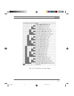
3-17
Installation
The 36-pin connection cable is NOT supplied with the printer and must not be
more than 2.5 meters long. Optional parallel interface cables are however
available.
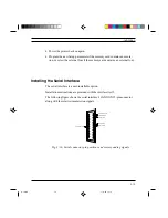
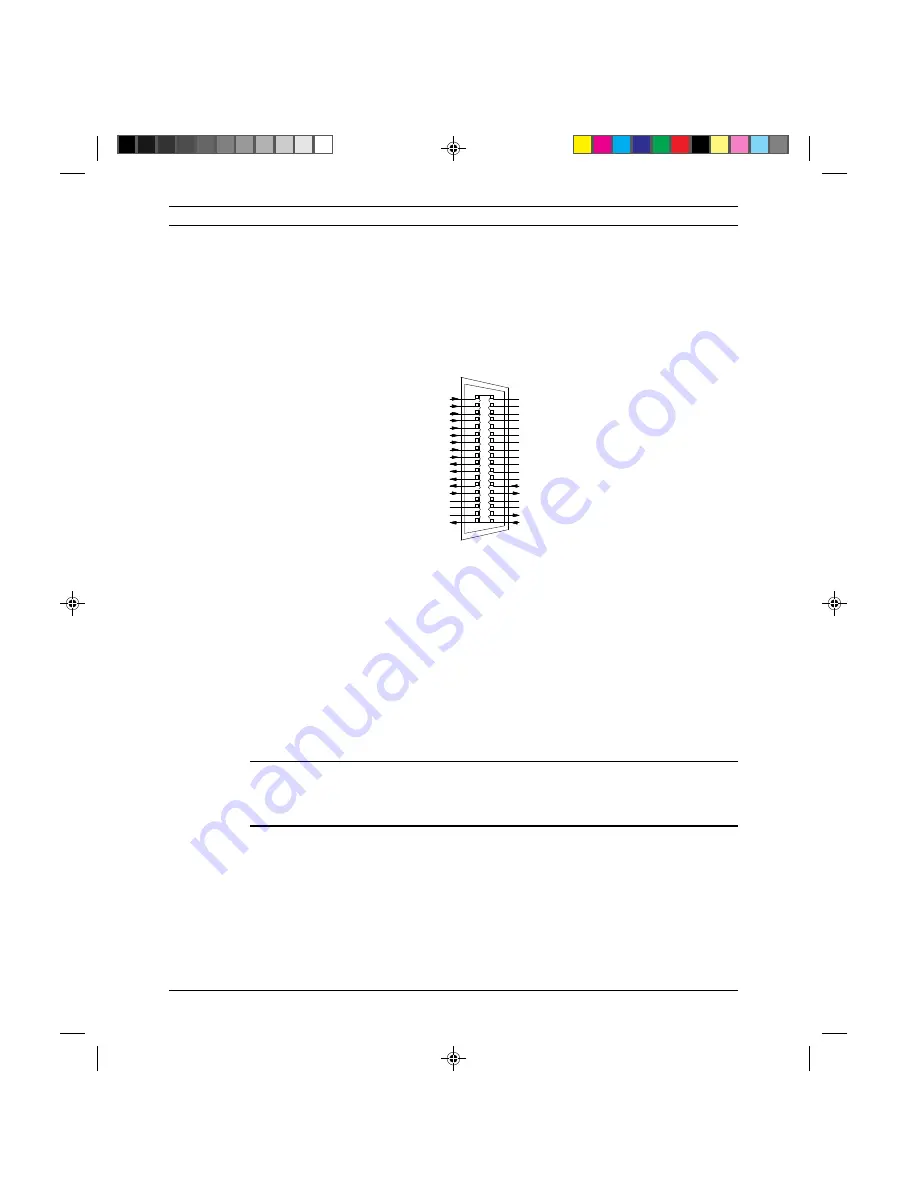
The following figure gives the connector's pin-out.
19 GROUND
20 GROUND
21 GROUND
22 GROUND
23 GROUND
24 GROUND
25 GROUND
26 GROUND
27 GROUND
28 GROUND
29 GROUND
30 GROUND
31 INIT.
32 ERROR
33 LOGIC GROUND
34 NC
35 +5 V (PULL-UP; 3.3K ohm)
36 INPUT / SELECT IN
FRAME GROUND 17
ACKNOWLEDGE 10
AUTOFEED XT 14
PAPER EMPTY 12
LOGIC GROUND 16
STROBE 01
DATA 1 03
DATA 2 04
DATA 3 05
DATA 4 06
DATA 5 07
DATA 6 08
DATA 7 09
BUSY 11
NC 15
+5 V 18
ON LINE 13
DATA 0 02
Powering off the Printer
Before powering off the printer make sure the print head is at the far right-hand
side of the carriage. It should automatically reach this position after a few
seconds of printer inactivity. The purpose for this is to tightly seal the print
nozzles to prevent the ink inside them from drying-out.
NOTE: If the personal computer is powered off while the printer is still on, the
printer will automatically reset itself. If the printer is powered off during the
reset phase, the print head may stop outside its parking position.
It is therefore suggested to power off the printer before the personal computer.
Fig. 3-18: Parallel connector pin positions and corresponding signals
S-3.PM5
11/7/94, 17:15
17
Содержание DECcolorwriter 120ic
Страница 58: ...3 21 Installation Fig 3 21 Fonts selector switches settings S 3 PM5 11 7 94 17 16 21 ...
Страница 59: ...3 22 Installation Fig 3 22 Character sets selector switches settings S 3 PM5 11 7 94 17 16 22 ...
Страница 60: ...3 23 Installation Fig 3 23 Character sets selector switches settings S 3 PM5 11 7 94 17 16 23 ...
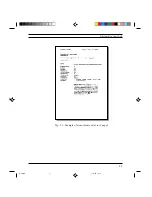
Страница 69: ...5 3 Diagnostics and Tests Fig 5 1 Example of monochrome print test page 1 S 5 PM5 11 7 94 17 18 3 ...
Страница 78: ...7 3 Electrical Interconnections Fig 7 1 Main board S 7 PM5 3 14 97 3 38 PM 3 ...


