


8-1
GP-2401/2501/2601 Series User Manual
Chapter
8
Maintenance
1. Regular Cleaning
2. Periodic Check Points
3. Changing the Backlight
When the surface or the frame of the display gets dirty, soak a soft cloth in water
with a neutral detergent, wring the cloth tightly, and wipe the display.
•
Do not use paint thinner, organic solvents, or a strong acid compound to clean the unit.
•
Do not use hard or pointed objects to operate the touch-screen panel, since it can dam-
age the panel surface.
The installation gasket protects the GP and improves its water resistance. For
instructions on installing the GP's gasket, refer to
Chapter 3 "Installation and Wiring"
A gasket which has been used for a long period of time may have
scratches or dirt on it, and could have lost much of its water resis-
tance. Be sure to change the gasket at least once a year, or when
scratches or dirt become visible.
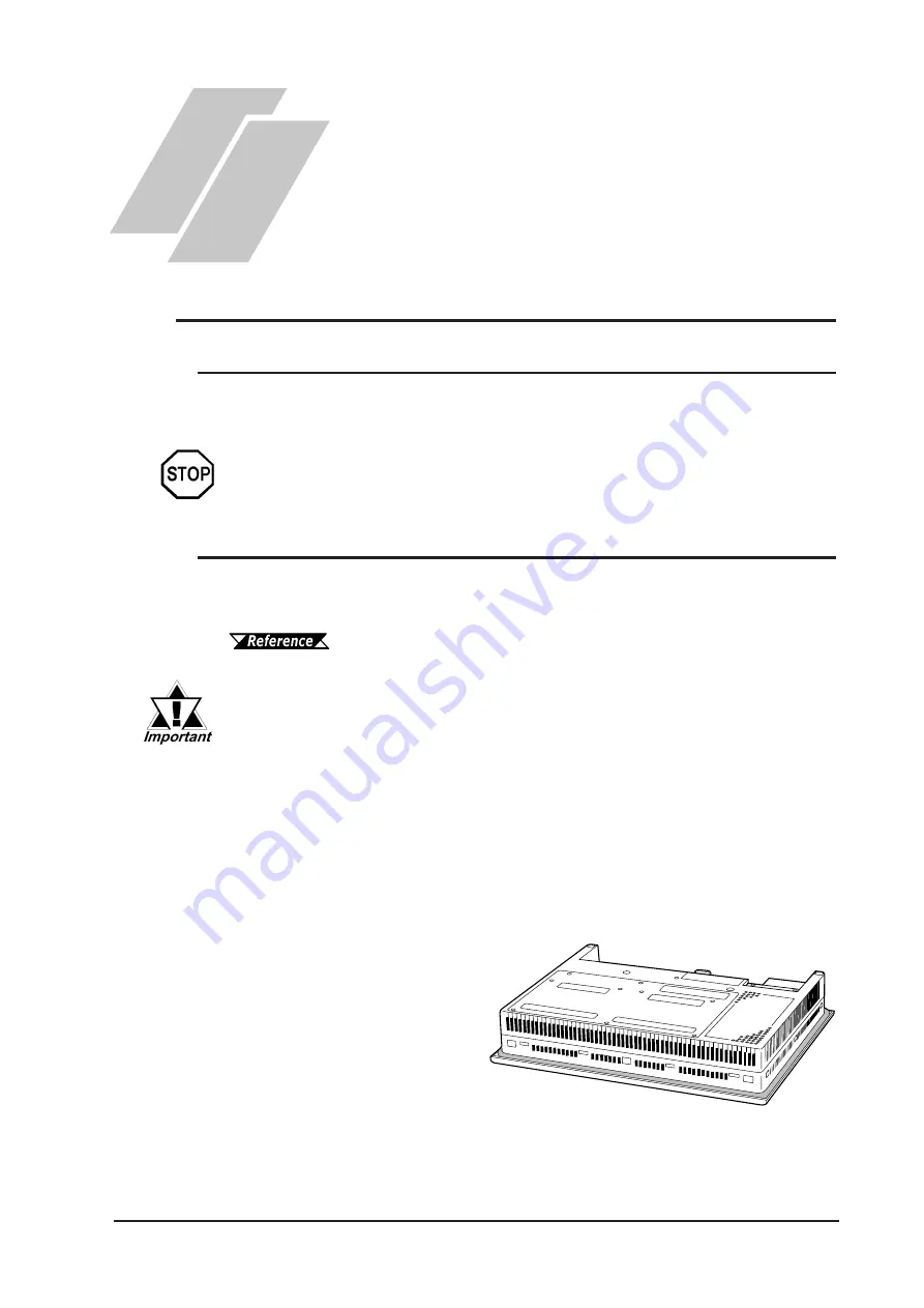
Installation Gasket Attachment Procedure
(The illustrations below show the procedures for the GP-2501T/GP-2501S/GP-
2601T models. However, these procedures are also the same for the GP-2401T.)
1) Place the GP on a flat,
level surface facing the
display face downwards.
2) Remove the gasket from
the GP.
8.1
Regular Cleaning
8.1.1 Cleaning the Display
8.1.2 Installation Gasket Check/Replacement
Содержание GP-2401 Series
Страница 1: ...GP 2401 2501 2601 Series User Manual Digital Electronics Corporation ...
Страница 25: ...Memo ...
Страница 69: ...Memo ...
Страница 103: ...Memo ...
Страница 129: ...Memo ...
Страница 137: ...Chapter 8 Maintenance GP 2401 2501 2601 Series User Manual 8 8 Memo ...


