JetBox-FloydSC User Manual rev 0.1
Page 20
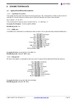
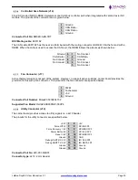
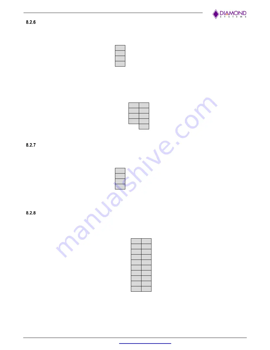
Controlled Area Network (J14)
Floyd SC model (FLDSC-BB02) implements one CAN bus controller port when integrated with Jetson Xavier NX
module. The pinouts of the connector are as given below:
1
Ground
2
CAN Data -
3
CAN Data +
4
Ground
Connector Part No
: BM04B-GHS-TBT
DSC Mating cable
: 6981182
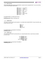
The CAN cable 6981182 has the near end terminated with the mating connector GHR-04V-S & the far end with a
DB9M. When the cable is used to access the CAN port, the DB9M follows the pinouts as shown below:
Ground
6
1
No Connect
CAN Data+
7
2
CAN Data-
No Connect
8
3
Ground
No Connect
9
4
No Connect
5
No Connect
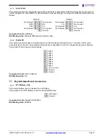
Fan Connector (J17)
Active thermal solution is not part of the system. However, to support active solutions, carrier board provides the
provision for this with a fan connector. The pinouts for the fan connector are specified below.
1
PWM
2
Tachometer
3
+5V
4
Ground
Connector Part Number
: Molex# 0533980471-2
Supported Fan Model
: Delta# ASB0305HP-00CP4
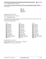
Utility Connector (J12)
The carrier board provides access to utility signals on a 2x10 header.
The pinouts for the utility connector are specified below.
+3.3V
1
2
+5V
Force Off 5V
3
4
SPI SS 3P3
Force Recovery 1,8V
5
6
SPI MISO 3P3
Power Button 5V
7
8
SPI CLK 3P3
Reset 1.8V
9
10
SPI MOSI 3P3
Ground
11 12
GND
Debug UART RX 3.3V
13 14
I2C CLK 3P3
Debug UART TX 3,3V
15 16
I2C DATA 3P3
Ground
17 18
Ground
Ground
19 20
Ground
Connector Part No
: 220-97-36GB01
Connector type
: 2x10, 2 mm Header

