JetBox-FloydSC User Manual rev 0.1
Page 29
Installing FloydSC inside the JetBox
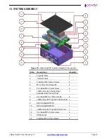
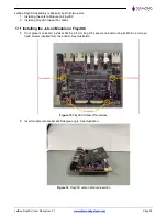
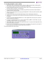
1. Install 4x M3 x 8mm F/F stand-offs at location 4 inside the JetBox enclosure body by inserting 4x M3 x
6mm screws at location 3 from outside the enclosure on its bottom side.
2. Descend the FloydSC with Jetson module into the JetBox & align the board mounting holes with the F/F
stand-offs installed at location 4 in the step above.
3. Secure the FloydSC PCB assembly on the JetBox using 4x M3 x 6mm pan head screws at location 5
inserted from the top side of the PCB.
4. Align the internal heat spreader to the previously installed 4x M2.5 x 6.5mm stand-offs. Insert the 4x M2.5
x 10mm at location 7
5. Remove the thermal line from the thermal pad and apply it on the heat spreader at location 8.
6. Install the Screw Terminal PCB to the front panel of the enclosure using 2x M3 x 6mm pan head screws
at location 8.
7. Connect one end of the cable DSC# 6981330 at J11 of the FloydSC PCB & the other end to rear side of
Screw Terminal PCB at location 9.
8. Connect the cable DSC# 6981075 at J13 of the FloydSC PCB & the DB9M-1 to the RS-232 cut out and
the DB9M-2 at the RS-232/485 cut out of the front panel.
9. Align the DIN bracket on the rear side of the enclosure at location 13 and secure the bracket with 2x M3 x
6mm flat head screws at location 14.
10. Finally, cover the entire assembly with the top heat sink cover aligning it to the screw holes at location 11.
Secure the heat sink with 4x M3 x 6mm pan head screws at location 12
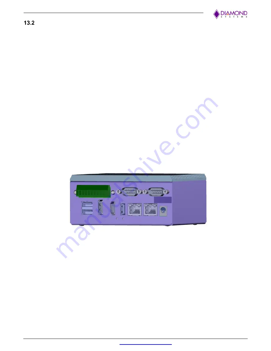
The fully assembled system looks as below:

