JetBox-FloydSC User Manual rev 0.1
Page 5
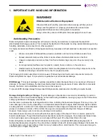
Damage During Installation on a PC/104 Stack
: Damage on boards can also occur while installing the board in
a PC/104 Stack A common cause of damage occurs when the connector pins are misaligned with their
corresponding interfaces on the stack.
For example, during installation, if a PC/104 board pin-mapping is misaligned/shifted by 1 row or 1 column, it can
cause the
12V power and Ground signal lines on the bus to contact the wrong pins on the board and damage
components linked to the data bus lines.
Bent Connector Pins
: This type of problem can be resolved by re-bending the pins to their original shape using
needle-nose pliers.
The most common cause of a bent connector pin is when the board is pulled off a stack by tugging it at angles
from one end of the connector to the other, to release it off the stack. Tugging the board off the stack in this
manner can bend the pin(s) significantly.
A similar situation can occur when pulling a ribbon cable off a pin header. If the pins are bent too severely,
bending them back can cause them to weaken or break. In this case, the connector must be replaced.
Power Damages
: There are various causes of power-specific damages that can occur while handling the board.
Some common causes such as
–a metal screwdriver tip slipping, or a screw dropping onto the board while it is
powered-up, causes a short between a power pin and a signal pin on a component.
These faults can cause over-voltage/power supply problems besides other causes described below.
To avoid such damages, assembly operations must be performed when the system is powered off.
Power Supply Wired Backwards
: Diamond Systems power supplies and boards are not designed to withstand a
reverse power supply connection. This will destroy almost all ICs connected to the power supply. In this case, the
board will likely be irreparable and must be replaced. A chip destroyed by reverse or excessive power will often
have a visible hole or show some deformation on the surface due to vaporization inside the package.
Overvoltage on Digital I/O Line
: If a Digital I/O signal is connected to a voltage above the maximum specified
voltage, the digital circuitry can be damaged. The acceptable voltage range, on most Diamond Systems boards
connected to digital I/O signals is 0-5V, with overvoltage protection up to 5.5V (-0.5 to 5.5V). Overvoltage beyond
this limit can damage the circuitry.
Other considerations are Logic Signals, which are typically generated between 12V to 24V.
If a Digital I/O Line of 12V to 24V is connected to a 5V logic chip, the chip will be damaged, and the damage could
extend to other chips in the circuit.
IMPORTANT!
Always check power connections twice before powering up!

