Chapter 12 Description of Parameter Settings
CT2000 Series
12.1-07-2
this setting is less than start frequency (Pr.01-09), the start-point for DC brake will start from the
min. frequency.
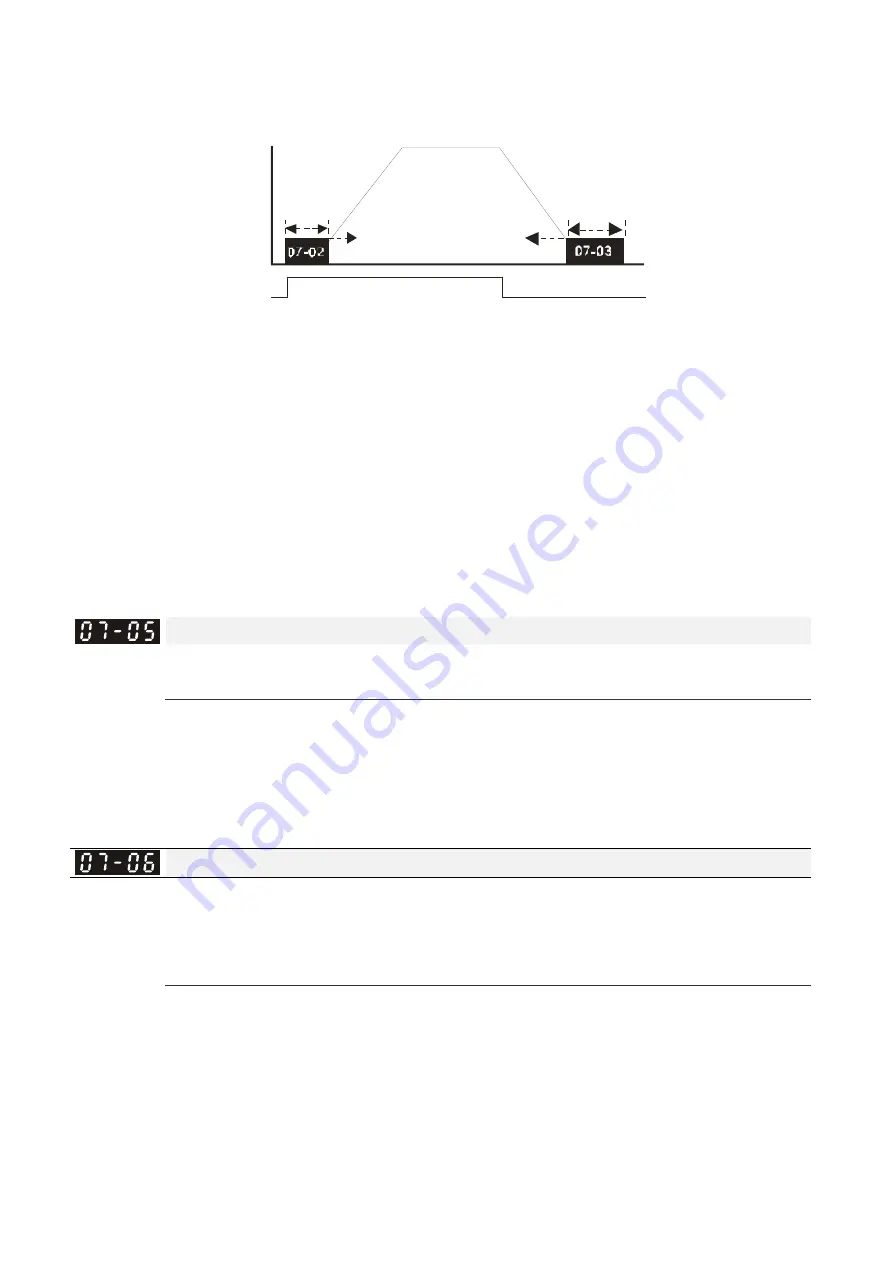
ON
OFF
01-09
07-04
Output frequen cy
Run /Stop
Time
DC Brake Time
DC Brak Time
during St opping
Minimum
out put
frequen cy
Start-point for
DC brake
time during
stopping
DC Brake at Start-up is used for loads that may move before the AC drive starts, such as fans and
pumps. Under such circumstances, DC Brake can be used to hold the load in position before
setting it in motion.
DC Brake at stop is used to shorten the stopping time and also to hold a stopped load in position,
such as crane or cutting machine.
Voltage Incrasing Gain
Factory Setting: 100
Settings 1~200%
When the user is using speed tracking, adjut Pr07-05 to slow down the increasing of voltage if
there are errors such as oL or ocv. Then the speed tracking time will be longer and the Pr07-09
Pivot Point of the Speed Tracking of the Current 20~200%, factory setting 50. If the pivot point of
the user is higher than the Pr06-03 pivot point of the oc stall, then the drive will choose the pivot
point of Pr06-03 as the highest pivot point of the speed tracking.
Restart after Momentary Power Loss
Factory Setting: 0
Settings 0: No function
1: Speed search for last frequency command
2: Speed search for the minimum output frequency
This parameter determines the operation mode when the AC motor drive restarts from a
momentary power loss.
The power connected to the drive may power off momentarily due to many reasons. This function
allows the drive to keep outputting after power is on again after power off and won’t cause drive
stops.
Setting 1: Operation continues after momentary power loss, speed search starts with the Master
Frequency reference value after drive output frequency and motor rotator speed is synchronous.
The motor has the characteristics of big inertia and small obstruction. For example, in the
Содержание CT2000 Series
Страница 5: ...Chapter 1 Introduction CT2000 Series 1 2 Model Name VFD 750 CT 43 F 00 A6 Serial Number...
Страница 22: ...Chapter 1 Introduction CT2000 Series 1 19 Digital Keypad KPC CC01 KPC CE01 Unit mm inch...
Страница 23: ...Chapter 1 Introduction CT2000 Series 1 20 This page intentionally left blank...
Страница 41: ...Chapter 4 Wiring CT2000 Series 4 6 This page intentionally left blank...
Страница 71: ...Chapter 7 Optional Accessories CT2000 Series 7 18 Wall Mounting Embedded Mounting...
Страница 87: ...Chapter 8 Optional Cards CT2000 Series 8 8 PG Card intallation...
Страница 88: ...Chapter 8 Optional Cards CT2000 Series 8 9 Disconneting the extension card...
Страница 92: ...Chapter 8 Optional Cards CT2000 Series 8 13 PG2 Wiring Diagram...
Страница 95: ...Chapter 8 Optional Cards CT2000 Series 8 16 PG2 Wiring Diagram...
Страница 117: ...Chapter 8 Optional Cards CT2000 Series 8 38 This page intentionally left blank...
Страница 121: ...Chapter 9 Specifications CT2000 Series 9 4 Frame B 370 0 140 0 Frame C 180 0 500 0 Frame D 180 0 660 0 Figure 1...
Страница 259: ...Chapter 12 Description of Parameter Settings CT2000 Series 12 1 03 11...
Страница 260: ...Chapter 12 Description of Parameter Settings CT2000 Series 12 1 03 12...
Страница 263: ...Chapter 12 Description of Parameter Settings CT2000 Series 12 1 03 15...
Страница 266: ...Chapter 12 Description of Parameter Settings CT2000 Series 12 1 03 18...
Страница 397: ...Chapter 13 Warning Codes CT2000 Series 13 8 This page intentionally left blank...
Страница 407: ...Chapter 14 Fault Codes and Descriptions CT2000 Series 14 10 This page intentionally left blank...
Страница 489: ...Chapter 16 PLC Function CT2000 Series 16 48 LD X1 Load Contact a of X1 OUT Y1 Drive Y1 coil...
Страница 591: ...Chapter 16 PLC Function CT2000 Series 16 150 Step 3 Physical configuration CT2000 Step 4 Write to PLC program...
Страница 592: ...Chapter 16 PLC Function CT2000 Series 16 151...
Страница 594: ...Chapter 16 PLC Function CT2000 Series 16 153...
Страница 597: ...Chapter 16 PLC Function CT2000 Series 16 156 This page intentionally left blank...
Страница 633: ...Chapter 19 EMC Standard Installation Guide CT2000 Series 19 20 This page intentionally left blank...


