Chapter 18 Suggestions and Error Corrections for Standard AC Motor Drives
CT2000 Series
18-11
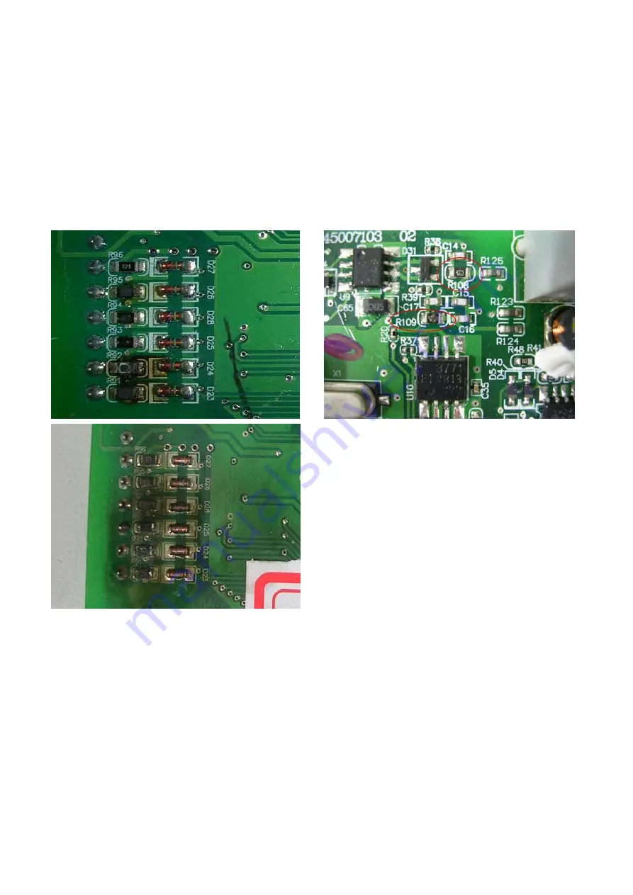
18-7 Multi-function Input/Output Terminals Problem
Multi-function input/output terminal errors are generally caused by over usage of terminals and
not following specifications. Please be aware of the possible damages that errors on multi-function
input/output terminals may cause to your drives:
1. Input/output circuit may burns out when the terminal usage exceeds its limit.
Solution:
Refer to the user manual for multi-function input output terminals usage and follow the specified
voltage and current. DO NOT exceed the specification limits.
Содержание CT2000 Series
Страница 5: ...Chapter 1 Introduction CT2000 Series 1 2 Model Name VFD 750 CT 43 F 00 A6 Serial Number...
Страница 22: ...Chapter 1 Introduction CT2000 Series 1 19 Digital Keypad KPC CC01 KPC CE01 Unit mm inch...
Страница 23: ...Chapter 1 Introduction CT2000 Series 1 20 This page intentionally left blank...
Страница 41: ...Chapter 4 Wiring CT2000 Series 4 6 This page intentionally left blank...
Страница 71: ...Chapter 7 Optional Accessories CT2000 Series 7 18 Wall Mounting Embedded Mounting...
Страница 87: ...Chapter 8 Optional Cards CT2000 Series 8 8 PG Card intallation...
Страница 88: ...Chapter 8 Optional Cards CT2000 Series 8 9 Disconneting the extension card...
Страница 92: ...Chapter 8 Optional Cards CT2000 Series 8 13 PG2 Wiring Diagram...
Страница 95: ...Chapter 8 Optional Cards CT2000 Series 8 16 PG2 Wiring Diagram...
Страница 117: ...Chapter 8 Optional Cards CT2000 Series 8 38 This page intentionally left blank...
Страница 121: ...Chapter 9 Specifications CT2000 Series 9 4 Frame B 370 0 140 0 Frame C 180 0 500 0 Frame D 180 0 660 0 Figure 1...
Страница 259: ...Chapter 12 Description of Parameter Settings CT2000 Series 12 1 03 11...
Страница 260: ...Chapter 12 Description of Parameter Settings CT2000 Series 12 1 03 12...
Страница 263: ...Chapter 12 Description of Parameter Settings CT2000 Series 12 1 03 15...
Страница 266: ...Chapter 12 Description of Parameter Settings CT2000 Series 12 1 03 18...
Страница 397: ...Chapter 13 Warning Codes CT2000 Series 13 8 This page intentionally left blank...
Страница 407: ...Chapter 14 Fault Codes and Descriptions CT2000 Series 14 10 This page intentionally left blank...
Страница 489: ...Chapter 16 PLC Function CT2000 Series 16 48 LD X1 Load Contact a of X1 OUT Y1 Drive Y1 coil...
Страница 591: ...Chapter 16 PLC Function CT2000 Series 16 150 Step 3 Physical configuration CT2000 Step 4 Write to PLC program...
Страница 592: ...Chapter 16 PLC Function CT2000 Series 16 151...
Страница 594: ...Chapter 16 PLC Function CT2000 Series 16 153...
Страница 597: ...Chapter 16 PLC Function CT2000 Series 16 156 This page intentionally left blank...
Страница 633: ...Chapter 19 EMC Standard Installation Guide CT2000 Series 19 20 This page intentionally left blank...


