Chapter 16 PLC Function
CT2000 Series
16-121
16- 8 CANopen Master control applications
Control of a simple multi-axis application is required in certain situations. If the device supports the
CANopen protocol, a CT2000 can serve as the master in implementing simple control (position,
speed, homing, and torque control). The setting method comprises the following seven steps:
Step 1: Activating CANopen Master functions
1.
Parameter 09-45=1 (initiates Master functions); restart power after completing setting, the status bar
on the KPC-CC01 digital keypad will display "CAN Master".
2.
Parameter 00-02=6 reset PLC (please note that this action will reset the program and PLC registers
to the default values)
3.
Turn power off and on again.
4.
Use the KPC-CC01 digital keypad to set the PLC control mode as
"PLC Stop"
(if the KPC-CE01
digital keypad is used, set as "PLC 2"; if a newly-introduced driver is used, the blank internal PLC
program will cause a PLFF warning code to be issued).
Step 2: Master memory settings
1. After connecting the 485 communications cable, use WPL Soft to set the PLC
status
as Stop (if the
PLC mode has been switched to the
"PLC Stop"
mode, the PLC
status
should already be Stop)
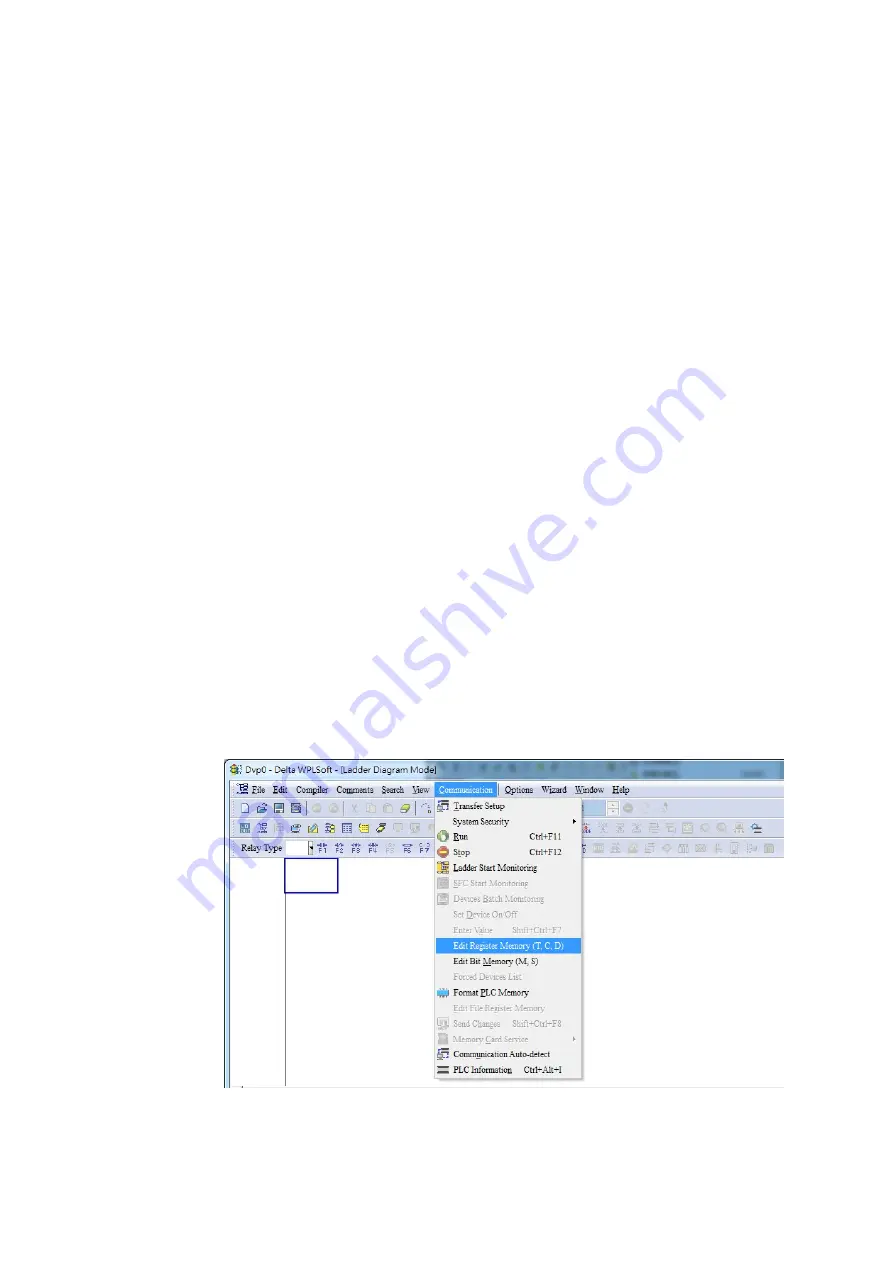
2. Set the address and corresponding station number of the slave station to be controlled. For instance,
if it is wished to control two slave stations (a maximum of 8 stations can be controlled simultaneously),
and the station numbers are 21 and 22, it is only necessary to set D2000 and D2100 as 20 and 21,
and then set D2200, D2300, D2400, D2500, D2600, and D2700 as 0. The setting method involves
use of the PLC's WPL editing software WPL as follows:
Open WPL and implement
communications > register edit (T C D)
function
Содержание CT2000 Series
Страница 5: ...Chapter 1 Introduction CT2000 Series 1 2 Model Name VFD 750 CT 43 F 00 A6 Serial Number...
Страница 22: ...Chapter 1 Introduction CT2000 Series 1 19 Digital Keypad KPC CC01 KPC CE01 Unit mm inch...
Страница 23: ...Chapter 1 Introduction CT2000 Series 1 20 This page intentionally left blank...
Страница 41: ...Chapter 4 Wiring CT2000 Series 4 6 This page intentionally left blank...
Страница 71: ...Chapter 7 Optional Accessories CT2000 Series 7 18 Wall Mounting Embedded Mounting...
Страница 87: ...Chapter 8 Optional Cards CT2000 Series 8 8 PG Card intallation...
Страница 88: ...Chapter 8 Optional Cards CT2000 Series 8 9 Disconneting the extension card...
Страница 92: ...Chapter 8 Optional Cards CT2000 Series 8 13 PG2 Wiring Diagram...
Страница 95: ...Chapter 8 Optional Cards CT2000 Series 8 16 PG2 Wiring Diagram...
Страница 117: ...Chapter 8 Optional Cards CT2000 Series 8 38 This page intentionally left blank...
Страница 121: ...Chapter 9 Specifications CT2000 Series 9 4 Frame B 370 0 140 0 Frame C 180 0 500 0 Frame D 180 0 660 0 Figure 1...
Страница 259: ...Chapter 12 Description of Parameter Settings CT2000 Series 12 1 03 11...
Страница 260: ...Chapter 12 Description of Parameter Settings CT2000 Series 12 1 03 12...
Страница 263: ...Chapter 12 Description of Parameter Settings CT2000 Series 12 1 03 15...
Страница 266: ...Chapter 12 Description of Parameter Settings CT2000 Series 12 1 03 18...
Страница 397: ...Chapter 13 Warning Codes CT2000 Series 13 8 This page intentionally left blank...
Страница 407: ...Chapter 14 Fault Codes and Descriptions CT2000 Series 14 10 This page intentionally left blank...
Страница 489: ...Chapter 16 PLC Function CT2000 Series 16 48 LD X1 Load Contact a of X1 OUT Y1 Drive Y1 coil...
Страница 591: ...Chapter 16 PLC Function CT2000 Series 16 150 Step 3 Physical configuration CT2000 Step 4 Write to PLC program...
Страница 592: ...Chapter 16 PLC Function CT2000 Series 16 151...
Страница 594: ...Chapter 16 PLC Function CT2000 Series 16 153...
Страница 597: ...Chapter 16 PLC Function CT2000 Series 16 156 This page intentionally left blank...
Страница 633: ...Chapter 19 EMC Standard Installation Guide CT2000 Series 19 20 This page intentionally left blank...


