


TMC 188/40 Motion Control Module
Hardware Information
Delta Computer Systems, Inc. 360/254-8688
47
Module Jumpers and External Wiring
The TMC 188/40 can be placed in any TI505 slot. It appears to the P/C as a Special Function
Interface Chip (SFIC) device. External power supplies must be provided for both the transducer
inputs and drive outputs. The power supplies must 5 volts and ± 15 volts with at least 500
mA. Do not connect the power supplies to any other loads, if possible. This precaution will separate
the P/C system from any noise or electrical faults on the wires going to the transducers or drives.
When wiring the system it is important the axes extend when a positive voltage or current is sent to
the drive. The extend direction is defined as the direction which causes the transducer or other type
of sensor to return increasing counts. The extend direction on a magnetostrictive transducer is away
from the transmitting end.
The wiring information later in this manual has wire color code data for the Temposonics® brand of
magnetostrictive transducers and cables supplied by Delta Computer Systems, Inc.
NOTE:
Noise problems with magnetostrictive transducers may be reduced by connecting a 220 Ohm
resistor between the interrogation pulse and common. Locate the resistor as close to the
transducer as possible.
CAUTION
: Do not connect the drive outputs to the drives until the extend and retract limits have been
computed and the P/C has properly initialized the TMC 188/40 with these limits.
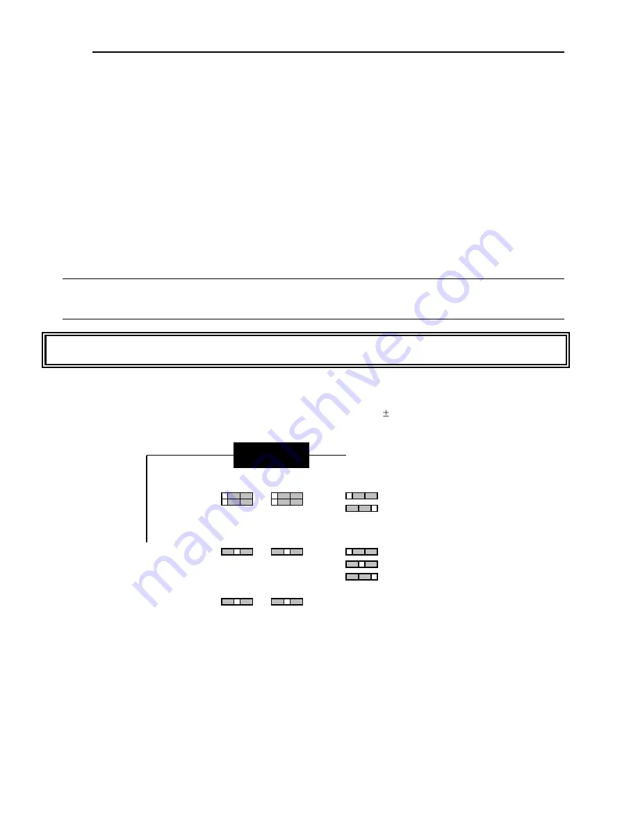
Drive Selection
The default drive configuration is current mode with a range of 50 milliamps. To change the output
configuration change the jumper as follows:
P12
P13
P14
P15
P16
P18
P17
P19
Current Mode (default)
Voltage Mode
± 25mA ± 2.5 Volts
± 50mA ± 5.0 Volts (default)
±100mA ±10.0 Volts
Output Level
Output Mode
DB-15S
P12 Axis 1 Mode
P13 Axis 2 Mode
P14 Axis 3 Mode
P15 Axis 4 Mode
P16 Axis 1 Output Level
P17 Axis 2 Output Level
P18 Axis 3 Output Level
P19 Axis 4 Output Level


