Dell PowerEdge R630 Скачать руководство пользователя страница 31

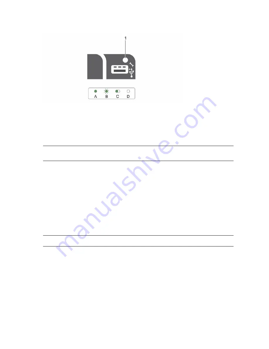
Figure 13. iDRAC Direct LED indicator

1.

iDRAC Direct status indicator

The iDRAC Direct LED indicator table describes iDRAC Direct activity when configuring iDRAC Direct by 
using the management port (USB XML Import).

Table 13. iDRAC Direct LED indicators

Convention

iDRAC Direct 

LED indicator 

pattern

Condition

A

Green

Turns green for a minimum of two seconds to indicate the start and 
end of a file transfer.

B

Flashing green

Indicates file transfer or any operation tasks.

C

Green and turns 
off

Indicates that the file transfer is complete.

D

Not lit

Indicates that the USB is ready to be removed or that a task is 
complete.

The following table describes iDRAC Direct activity when configuring iDRAC Direct by using your laptop 
and cable (Laptop Connect):

Table 14. iDRAC Direct LED indicator patterns

iDRAC Direct LED 

indicator pattern

Condition

Solid green for two 
seconds

Indicates that the laptop is connected.

Flashing green (on 
for two seconds and 
off for two seconds) 

Indicates that the laptop connected is recognized.

Turns off

Indicates that the laptop is unplugged.

31

Содержание PowerEdge R630

Страница 1: ...Dell PowerEdge R630 Owner s Manual Regulatory Model E26S Series Regulatory Type E26S001 ...

Страница 2: ... the problem WARNING A WARNING indicates a potential for property damage personal injury or death 2016 Dell Inc All rights reserved This product is protected by U S and international copyright and intellectual property laws Dell and the Dell logo are trademarks of Dell Inc in the United States and or other jurisdictions All other marks and names mentioned herein may be trademarks of their respecti...

Страница 3: ... NIC indicator codes 27 Power supply unit indicator codes 27 iDRAC Direct LED indicator codes 30 Quick Sync indicator codes 32 Locating Service Tag of your system 33 2 Documentation resources 34 3 Technical specifications 37 Chassis dimensions 37 Chassis weight 38 Processor specifications 38 PSU specifications 38 System battery specifications 39 Expansion bus specifications 39 Memory specification...

Страница 4: ...tions to manage the pre operating system applications 49 System Setup 49 Viewing System Setup 50 System Setup details 50 System BIOS 50 iDRAC Settings utility 74 Device Settings 74 Dell Lifecycle Controller 75 Embedded system management 75 Boot Manager 75 Viewing Boot Manager 75 Boot Manager main menu 76 PXE boot 76 6 Installing and removing system components 77 Safety instructions 77 Before worki...

Страница 5: ...talling a 1 8 inch hard drive into a hard drive carrier 106 Optical drive optional 106 Removing the optional optical drive 106 Installing the optional optical drive 107 Removing the slim optical drive blank 108 Installing the slim optical drive blank 109 Cooling fans 110 Removing a cooling fan 110 Installing a cooling fan 111 Internal USB memory key optional 112 Replacing the optional internal USB...

Страница 6: ...ower supply unit 151 System battery 152 Replacing the system battery 152 Hard drive backplane 154 Removing the hard drive backplane 154 Installing the hard drive backplane 161 Control panel assembly 163 Removing the control panel board eight hard drive system 163 Installing the control panel board eight hard drive system 164 Removing the control panel eight hard drive system 165 Installing the con...

Страница 7: ...shooting iDRAC Direct USB XML configuration 191 Troubleshooting iDRAC Direct Laptop connection 191 Troubleshooting a serial I O device 192 Troubleshooting a NIC 192 Troubleshooting a wet system 193 Troubleshooting a damaged system 194 Troubleshooting the system battery 195 Troubleshooting power supply units 195 Troubleshooting power source problems 196 Power supply unit problems 196 Troubleshootin...

Страница 8: ...Documentation feedback 206 Accessing system information by using QRL 206 Quick Resource Locator for R630 207 8 ...

Страница 9: ... hard drives or eight x 2 5 inch hard drives Four optional NVMe Express Flash PCIe SSDs 24 DIMM slots supporting up to 1536 GB of memory Two AC or DC redundant power supply units NOTE The Dell PowerEdge R630 system supports hot swappable hard drives Supported configurations for the PowerEdge R630 system The Dell PowerEdge R630 system supports the following configurations 9 ...

Страница 10: ...Figure 1 Supported configurations for the PowerEdge R630 system Front panel 10 ...

Страница 11: ...indicators The diagnostic indicators light up to display error status 2 System health indicator The system health indicator flashes amber when a system fault is detected 3 Power on indicator power button The power indicator turns on when the system power is on The power button controls the power supply output to the system NOTE On ACPI compliant operating systems turning off the system by using th...

Страница 12: ...es to the system or provides access to the iDRAC Direct features For more information see the Integrated Dell Remote Access Controller User s Guide at Dell com idracmanuals The port is USB 3 0 compliant 7 Information tag Contains system information such as service tag NIC MAC address for your reference The information tag is a slide out label panel 8 Hard drives 10 Up to ten 2 5 inch hot swappable...

Страница 13: ... turns on when the system power is on The power button controls the power supply output to the system NOTE On Advanced Configuration and Power Interface ACPI compliant operating systems turning off the system by using the power button causes the system to perform a graceful shutdown before power to the system is turned off 2 NMI button Enables you to troubleshoot software and device driver errors ...

Страница 14: ...evices are data only 6 SD vFlash media card slot Enables you to insert a vFlash media card 7 LCD menu buttons Enables you to navigate the control panel LCD menu 8 Information tag Contains system information such as service tag NIC MAC address for your reference The information tag is a slide out label panel 9 LCD panel Displays system ID status information and system error messages The LCD turns b...

Страница 15: ...PowerEdge R630 chassis 1 Diagnostic indicators 2 System health indicator 3 Power on indicator power button 4 NMI button 5 System identification button 6 Micro USB port 7 Information tag 8 Hard drives 24 9 Quick Sync Table 3 Front panel features of the 24 x 1 8 inch hard drive PowerEdge R630 chassis Item Indicator Button or Connector Icon Description 1 Diagnostic indicators The diagnostic indicator...

Страница 16: ...ing during POST press and hold the system ID button for more than five seconds to enter BIOS progress mode To reset the iDRAC if not disabled in F2 iDRAC setup press and hold the button for more than 15 seconds 6 Micro USB port Enables you to connect USB devices to the system or provides access to the iDRAC Direct features For more information see the Integrated Dell Remote Access Controller User ...

Страница 17: ...to a power source and an error is detected the LCD turns amber regardless of whether the system is turned on or off The LCD backlight is turned off when the system is in standby mode and can be turned on by pressing either the Select Left or Right button on the LCD panel The LCD backlight remains off if LCD messaging is turned off using the iDRAC utility the LCD panel or other tools Figure 5 LCD p...

Страница 18: ... enable DNS and to view domain addresses Two separate DNS entries are available Set error Select SEL to view LCD error messages in a format that matches the IPMI description in the SEL This enables you to match an LCD message with an SEL entry Select Simple to view LCD error messages in a simplified user friendly description For more information about error messages see the Dell Event and Error Me...

Страница 19: ...xpansion card slot riser 1 5 Serial connector 6 Video connector 7 USB ports 2 8 PCIe expansion card slot riser 2 9 Ethernet connectors 4 10 Power supply unit PSU1 11 Power supply unit PSU2 Table 5 Back panel features two PCIe expansion cards Item Indicator Button or Connector Icon Description 1 System identification button The identification buttons on the front and back panels can be used to loca...

Страница 20: ...l connector Enables you to connect a serial device to the system 6 Video connector Enables you to connect a VGA display to the system 7 USB ports 2 Enables you to connect USB devices to the system The ports are USB 3 0 compliant 8 PCIe expansion card slot riser 2 Enables you to connect a full height three fourth length PCIe expansion card See the Expansion card installation guidelines section 9 Et...

Страница 21: ...xpansion card slot riser 2 8 Video connector 9 USB port 2 10 LP PCIe expansion card slot riser 3 11 Ethernet connectors 4 12 Power supply PSU1 13 Power supply PSU2 Table 6 Back panel features three PCIe expansion cards Item Indicator Button or Connector Icon Description 1 System identification button The identification buttons on the front and back panels can be used to locate a particular system ...

Страница 22: ...em 4 LP PCIe expansion card slot riser 1 Enables you to connect a low profile LP PCIe expansion card See the Expansion card installation guidelines section 5 Serial connector Enables you to connect a serial device to the system 6 LP PCIe expansion card slot riser 2 Enables you to connect a low profile LP PCIe expansion card See the Expansion card installation guidelines section 7 Video connector E...

Страница 23: ...systems NOTE No diagnostic indicators are lit when the system is turned off To start the system plug it into a working power source and press the power button Table 7 Diagnostic indicators Icon Description Condition Corrective action Health indicator The indicator turns solid blue if the system is in good health None required The indicator flashes amber When the system is turned on When the system...

Страница 24: ...cator flashes amber if the system experiences a thermal error for example the ambient temperature is out of range or fan failure Ensure that none of the following conditions exist A cooling fan has been removed or has failed System cover cooling shroud EMI filler panel memory module blank or back filler bracket is removed Ambient temperature is too high External airflow is obstructed See the Getti...

Страница 25: ...n Flashes green twice per second Identifying drive or preparing for removal Off Drive ready for insertion or removal NOTE The drive status indicator remains off until all hard drives are initialized after the system is turned on Drives are not ready for insertion or removal during this time Flashes green amber and turns off Predicted drive failure Flashes amber four times per second Drive failed F...

Страница 26: ... Condition Flashes green twice per second Identifying drive or preparing for removal Off Drive ready for insertion or removal NOTE The drive status indicator remains off until all hard drives are initialized after the system is turned on Drives are not ready for insertion or removal during this time Flashes green amber and turns off Predicted drive failure Flashes amber four times per second Drive...

Страница 27: ...at its maximum port speed 1 Gbps or 10 Gbps C Link indicator is amber The NIC is connected to a valid network at less than its maximum port speed D Activity indicator is flashing green Network data is being sent or received Power supply unit indicator codes AC power supply units PSUs have an illuminated translucent handle that serves as an indicator and DC PSUs have an LED that serves as an indica...

Страница 28: ...rns off When hot adding a PSU the PSU handle flashes green five times at 4 Hz rate and turns off This indicates a PSU mismatch with respect to efficiency feature set health status and supported voltage NOTE Ensure that both the PSUs are of the same capacity CAUTION For AC PSUs use only PSUs with the Extended Power Performance EPP label on the back NOTE Mixing PSUs from previous generations of Dell...

Страница 29: ...must power down the system CAUTION AC PSUs support both 220 V and 110 V input voltages with the exception of Titanium PSUs which support only 220 V When two identical PSUs receive different input voltages they can output different wattages and trigger a mismatch CAUTION If two PSUs are used they must be of the same type and have the same maximum output power CAUTION Combining AC and DC PSUs is not...

Страница 30: ...ke a matched pair can result in an error condition and unexpected system shutdown To change from a High Output configuration to a Low Output configuration or vice versa you must power down the system CAUTION AC PSU support both 220 V and 110 V input voltages with the exception of Titanium PSU which support only 220 V When two identical PSU receive different input voltages they can output different...

Страница 31: ...file transfer or any operation tasks C Green and turns off Indicates that the file transfer is complete D Not lit Indicates that the USB is ready to be removed or that a task is complete The following table describes iDRAC Direct activity when configuring iDRAC Direct by using your laptop and cable Laptop Connect Table 14 iDRAC Direct LED indicator patterns iDRAC Direct LED indicator pattern Condi...

Страница 32: ...rapidly five times and turns off for one second when the activation button is pressed This pattern is repeated until the activation button is pressed again Indicates that the Quick Sync hardware is not responding properly Reseat the bezel If the problem persists see Getting help section Off Indicates that the Quick Sync feature is turned off Use the activation button to enable it If pressing the a...

Страница 33: ...ode and Service Tag number The Express Service Code and Service Tag are found on the front of the system by pulling out the information tag Alternatively the information may be on a sticker on the chassis of the system This information is used by Dell to route support calls to the appropriate personnel 33 ...

Страница 34: ...ons section in this document Dell com poweredgemanuals Configuring your system For information about iDRAC features configuring and logging in to iDRAC and managing your system remotely see the Integrated Dell Remote Access Controller User s Guide Dell com idracmanuals For information about installing the operating system see the operating system documentation Dell com operatingsystemmanuals For i...

Страница 35: ...Lifecycle Controller LCC see the Dell Lifecycle Controller User s Guide Dell com idracmanuals For information about partner programs enterprise systems management see the OpenManage Connections Enterprise Systems Management documents Dell com omconnectionsenterprisesystemsman agement For information about connections and client systems management see the OpenManage Connections Client Systems Manag...

Страница 36: ...n Understanding event and error messages For information about checking the event and error messages generated by the system firmware and agents that monitor system components see the Dell Event and Error Messages Reference Guide Dell com openmanagemanuals OpenManage software 36 ...

Страница 37: ...3 Technical specifications The technical and environmental specifications of your system are outlined in this section Chassis dimensions Figure 15 Chassis dimensions of PowerEdge R630 system 37 ...

Страница 38: ...ecifications The PowerEdge R630 system supports up to two Intel Xeon E5 2600 v3 or v4 product family processors PSU specifications The PowerEdge R630 system supports up to two AC or DC redundant power supply units PSUs Table 19 PSU specifications PSU Class Heat dissipation maximum Frequency Voltage 495 W AC Platinum 1908 BTU hr 50 60 Hz 100 240 V AC autoranging 750 W AC Platinum 2891 BTU hr 50 60 ...

Страница 39: ...8 Slot 1 Low Profile Half Length x16 Riser 3 Slot 2 Full height Three fourth Length x16 Slot 3 Low Profile Half Length x16 NOTE When using slot 1 on the riser ensure that both the processors are installed on the system NOTE Only a three fourth length card is supported for the PCIe expansion card slot slot 2 on riser 3 when no mini PERC card is installed Supported length with mini PERC card install...

Страница 40: ...tical drive The PowerEdge R630 system supports one optional SATA DVD ROM drive or DVD RW drive on 8 hard drive systems only Ports and connectors specifications USB ports The PowerEdge R630 system supports USB 2 0 compliant ports on the front panel USB 3 0 complaint ports on the back panel Internal USB 3 0 compliant port Table 22 USB specifications System Front panel Back panel Internal PowerEdge R...

Страница 41: ...y The PowerEdge R630 system supports two 15 pin VGA ports on the front and back panels Internal Dual SD Module The PowerEdge R630 system supports two optional flash memory card slots with an internal dual SD module NOTE One card slot is dedicated for redundancy Video specifications The PowerEdge R630 system supports Integrated VGA controller with 16 MB capacity Table 23 Resolution information for ...

Страница 42: ...tions Relative humidity Specifications Storage 5 to 95 RH with 33 C 91 F maximum dew point Atmosphere must be non condensing at all times Operating 10 to 80 relative humidity with 29 C 84 2 F maximum dew point Table 26 Maximum vibration specifications Maximum vibration Specifications Operating 0 26 Grms at 5 Hz to 350 Hz all operation orientations Storage 1 88 Grms at 10 Hz to 500 Hz for 15 min al...

Страница 43: ...he levels of particulates or gaseous pollution exceed the specified limitations and result in equipment damage or failure you may need to rectify the environmental conditions Re mediation of environmental conditions is the responsibility of the customer Table 30 Particulate contamination specifications Particulate contamination Specifications Air filtration Data center air filtration as defined by...

Страница 44: ...on the equipment NOTE Maximum of 145 W 22 core processor is supported in systems with eight 2 5 inch drives 2 PCI slot chassis and 75 W single wide active GPU Standard operating temperature restrictions Ambient temperature is restricted to 30 C for systems with eight 2 5 inches drives or ten 2 5 inch drives chassis with no PCIe SSD and a maximum of 160 W workstation processor Ambient temperature i...

Страница 45: ... C de rate maximum allowable temperature by 1 C per 125 m above 950 m 1 F per 228 ft NOTE When operating in the expanded temperature range system performance may be impacted NOTE When operating in the expanded temperature range ambient temperature warnings may be reported on the LCD panel and in the System Event Log Expanded operating temperature restrictions Do not perform a cold startup below 5 ...

Страница 46: ...and reduces the need for physical access to the system Options to set up iDRAC IP address You must configure the initial network settings based on your network infrastructure to enable the communication to and from iDRAC You can set up the IP address by using one of the following interfaces Interfaces Document Section iDRAC Settings utility See Dell Integrated Dell Remote Access Controller User s ...

Страница 47: ...ating system by using one of the following resources Table 34 Resources to install the operating system Resources Location Dell Systems Management Tools and Documentation media Dell com operatingsystemmanuals Dell Lifecycle Controller Dell com idracmanuals Dell OpenManage Deployment Toolkit Dell com openmanagemanuals Dell certified VMware ESXi Dell com virtualizationsolutions Supported operating s...

Страница 48: ...irmware on your system Prerequisites Ensure that you clear the web browser cache before downloading the drivers and firmware Steps 1 Go to Dell com support drivers 2 Under the Drivers Downloads section type the Service Tag of your system in the Service Tag or Express Service Code box NOTE If you do not have the Service Tag select Detect My Product to allow the system to automatically detect your S...

Страница 49: ...onment PXE Related Links System Setup Boot Manager Dell Lifecycle Controller PXE boot System Setup By using the System Setup screen you can configure the BIOS settings iDRAC settings and device settings of your system NOTE Help text for the selected field is displayed in the graphical browser by default To view the help text in the text browser press F1 You can access system setup by using two met...

Страница 50: ...is an interface to set up and configure the iDRAC parameters by using UEFI Unified Extensible Firmware Interface You can enable or disable various iDRAC parameters by using the iDRAC settings utility For more information about this utility see Integrated Dell Remote Access Controller User s Guide at Dell com idracmanuals Device Settings Enables you to configure device settings Related Links System...

Страница 51: ...to the installed memory Processor Settings Specifies information and options related to the processor such as speed and cache size SATA Settings Specifies options to enable or disable the integrated SATA controller and ports Boot Settings Specifies options to specify the boot mode BIOS or UEFI Enables you to modify UEFI and BIOS boot settings Network Settings Specifies options to change the networ...

Страница 52: ...ngs Related Links Boot Settings Boot Settings details Choosing the system boot mode Changing the boot order Boot Settings details The Boot Settings screen details are explained as follows Option Description Boot Mode Enables you to set the boot mode of the system CAUTION Switching the boot mode may prevent the system from booting if the operating system is not installed in the same boot mode If th...

Страница 53: ...IOS 1 From the System Setup Main Menu click Boot Settings and select Boot Mode 2 Select the boot mode you want the system to boot into CAUTION Switching the boot mode may prevent the system from booting if the operating system is not installed in the same boot mode 3 After the system boots in the specified boot mode proceed to install your operating system from that mode NOTE Operating systems mus...

Страница 54: ... the following steps 1 Turn on or restart your system 2 Press F2 immediately after you see the following message F2 System Setup NOTE If your operating system begins to load before you press F2 wait for the system to finish booting and then restart your system and try again 3 On the System Setup Main Menu screen click System BIOS 4 On the System BIOS screen click Network Settings Related Links Net...

Страница 55: ...ystem Setup Main Menu screen click System BIOS 4 On the System BIOS screen click Network Settings 5 On the Network Settings screen click UEFI iSCSI Settings Related Links UEFI iSCSI Settings UEFI iSCSI Settings details The UEFI ISCSI Settings screen details are explained as follows Option Description ISCSI Initiator Name Specifies the name of the iSCSI initiator iqn format ISCSI Device n n 1 to 4 ...

Страница 56: ...n is read only if the password jumper is not installed in the system Password Status Locks the system password This option is set to Unlocked by default TPM Security NOTE The TPM menu is available only when the TPM module is installed Enables you to control the reporting mode of the TPM The TPM Security option is set to Off by default You can only modify the TPM Status TPM Activation and Intel TXT...

Страница 57: ... Standard the BIOS uses the system manufacturer s key and certificates to authenticate pre boot images When Secure Boot policy is set to Custom the BIOS uses the user defined key and certificates Secure Boot policy is set to Standard by default Secure Boot Policy Summary Specifies the list of certificates and hashes that secure boot uses to authenticate images Related Links System Security Viewing...

Страница 58: ...diately after turning on or rebooting your system 2 On the System Setup Main Menu screen click System BIOS System Security 3 On the System Security screen verify that Password Status is set to Unlocked 4 In the System Password field type your system password and press Enter or Tab Use the following guidelines to assign the system password A password can have up to 32 characters The password can co...

Страница 59: ...ately after turning on or restarting your system 2 On the System Setup Main Menu screen click System BIOS System Security 3 On the System Security screen ensure that Password Status is set to Unlocked 4 In the System Password field alter or delete the existing system password and then press Enter or Tab 5 In the Setup Password field alter or delete the existing setup password and then press Enter ...

Страница 60: ...the System Information screen perform the following steps 1 Turn on or restart your system 2 Press F2 immediately after you see the following message F2 System Setup NOTE If your operating system begins to load before you press F2 wait for the system to finish booting and then restart your system and try again 3 On the System Setup Main Menu screen click System BIOS 4 On the System BIOS screen cli...

Страница 61: ...System BIOS Viewing Memory Settings Viewing Memory Settings To view the Memory Settings screen perform the following steps 1 Turn on or restart your system 2 Press F2 immediately after you see the following message F2 System Setup NOTE If your operating system begins to load before you press F2 wait for the system to finish booting and then restart your system and try again 3 On the System Setup M...

Страница 62: ... to Enabled memory interleaving is supported if a symmetric memory configuration is installed If the field is set to Disabled the system supports NUMA asymmetric memory configurations This option is set to Disabled by default Snoop Mode Specifies the Snoop Mode options The Snoop Mode options available are Home Snoop Early Snoop and Cluster on Die This option is set to Early Snoop by default This f...

Страница 63: ...izes the system for applications that need high utilization of sequential memory access This option is set to Enabled by default You can disable this option for applications that need high utilization of random memory access Hardware Prefetcher Enables or disables the hardware prefetcher This option is set to Enabled by default DCU Streamer Prefetcher Enables or disables the Data Cache Unit DCU st...

Страница 64: ... Brand Specifies the brand name Level 2 Cache Specifies the total L2 cache Level 3 Cache Specifies the total L3 cache Number of Cores Specifies the number of cores per processor Related Links Processor Settings Viewing Processor Settings SATA Settings You can use the SATA Settings screen to view the SATA settings of SATA devices and enable RAID on your system Related Links SATA Settings details Sy...

Страница 65: ...pe of drive attached to the SATA port Capacity Specifies the total capacity of the hard drive This field is undefined for removable media devices such as optical drives Port B Sets the drive type of the selected device For Embedded SATA settings in ATA mode set this field to Auto to enable BIOS support Set it to OFF to turn off BIOS support For AHCI or RAID mode BIOS support is always enabled Opti...

Страница 66: ... turn off BIOS support For AHCI or RAID mode BIOS support is always enabled Option Description Model Specifies the drive model of the selected device Drive Type Specifies the type of drive attached to the SATA port Capacity Specifies the total capacity of the hard drive This field is undefined for removable media devices such as optical drives Port F Sets the drive type of the selected device For ...

Страница 67: ...e hard drive This field is undefined for removable media devices such as optical drives Port I Sets the drive type of the selected device For Embedded SATA settings in ATA mode set this field to Auto to enable BIOS support Set it to OFF to turn off BIOS support For AHCI or RAID mode BIOS support is always enabled Option Description Model Specifies the drive model of the selected device Drive Type ...

Страница 68: ...en restart your system and try again 3 On the System Setup Main Menu screen click System BIOS 4 On the System BIOS screen click Integrated Devices Related Links Integrated Devices Integrated Devices details Integrated Devices details The Integrated Devices screen details are explained as follows Option Description USB 3 0 Setting Enables or disables the USB 3 0 support Enable this option only if y...

Страница 69: ...is a read only field If the Embedded Video Controller is the only display capability in the system that is no add in graphics card is installed then the Embedded Video Controller is automatically used as the primary display even if the Embedded Video Controller setting is set to Disabled SR IOV Global Enable Enables or disables the BIOS configuration of Single Root I O Virtualization SR IOV device...

Страница 70: ...Device 2 for the Serial Over LAN SOL feature To use console redirection by SOL configure the same port address for console redirection and the serial device NOTE Every time the system boots the BIOS syncs the serial MUX setting saved in iDRAC The serial MUX setting can independently be changed in iDRAC Loading the BIOS default settings from within the BIOS setup utility may not always revert the s...

Страница 71: ...em Setup NOTE If your operating system begins to load before you press F2 wait for the system to finish booting and then restart your system and try again 3 On the System Setup Main Menu screen click System BIOS 4 On the System BIOS screen click System Profile Settings Related Links System Profile Settings System Profile Settings details System Profile Settings details The System Profile Settings ...

Страница 72: ...option is set to 1x by default Uncore Frequency Enables you to select the Processor Uncore Frequency option Dynamic mode enables the processor to optimize power resources across the cores and uncore during runtime The optimization of the uncore frequency to either save power or optimize performance is influenced by the setting of the Energy Efficiency Policy option Energy Efficient Policy Enables ...

Страница 73: ...s Settings screen details are explained as follows Option Description System Time Enables you to set the time on the system System Date Enables you to set the date on the system Asset Tag Specifies the asset tag and enables you to modify it for security and tracking purposes Keyboard NumLock Enables you to set whether the system boots with the NumLock enabled or disabled This option is set to On b...

Страница 74: ...ed system 2 Press F2 during Power on Self test POST 3 On the System Setup Main Menu page click iDRAC Settings The iDRAC Settings screen is displayed Related Links iDRAC Settings utility Changing the thermal settings The iDRAC settings utility enables you to select and customize the thermal control settings for your system 1 Click iDRAC Settings Thermal 2 Under SYSTEM THERMAL PROFILE Thermal Profil...

Страница 75: ... configurations may not support the full set of features provided by the Dell Lifecycle Controller For more information about setting up the Dell Lifecycle Controller configuring hardware and firmware and deploying the operating system see the Dell Lifecycle Controller documentation at Dell com idracmanuals Related Links Dell Lifecycle Controller Boot Manager The Boot Manager screen enables you to...

Страница 76: ...tem Utilities Enables you to launch System Utilities menu such as System Diagnostics and UEFI shell Related Links Boot Manager Viewing Boot Manager One shot BIOS boot menu One shot BIOS boot menu enables you to select a one shot boot device to boot from the following options Launch Diagnostics BIOS Update File Explorer Reboot System Related Links Boot Manager System Utilities System Utilities cont...

Страница 77: ...ety instructions that are shipped with your product CAUTION Operating the system without the system cover can result in component damage NOTE Dell recommends that you always use a static mat and static strap while working on components inside the system NOTE To ensure proper operation and cooling all bays in the system and system fans must be populated always with either a component or with a blan...

Страница 78: ...l lock This is needed only if your system includes a bezel Phillips 1 screwdriver Phillips 2 screwdriver Wrist grounding strap You need the following tools to assemble the cables for a DC power supply unit AMP 90871 1 hand crimping tool or equivalent Tyco Electronics 58433 3 or equivalent Wire stripper pliers to remove insulation from size 10 AWG solid or stranded insulated copper wire NOTE Use al...

Страница 79: ...ease latch up and pull the left end of the bezel 4 Unhook the right end and remove the bezel Figure 16 Removing the optional front bezel 1 bezel lock 2 front bezel Figure 17 Removing the Quick Sync bezel 1 bezel lock 2 Quick Sync bezel Related Links Safety instructions Installing the optional front bezel 79 ...

Страница 80: ...s section Steps 1 Locate and remove the bezel key NOTE The bezel key is attached to the back of the bezel 2 Hook the right end of the bezel onto the chassis 3 Fit the free end of the bezel onto the system 4 Lock the bezel by using the key Figure 18 Installing the optional front bezel 1 bezel lock 2 front bezel 80 ...

Страница 81: ...structions section 2 Turn off the system including any attached peripherals 3 Disconnect the system from the electrical outlet and disconnect the peripherals 4 If installed remove the optional bezel For more information see the Removing the optional front bezel section Steps 1 Rotate the latch release lock counter clockwise to the unlocked position 2 Lift the latch toward the back of the system Th...

Страница 82: ... all internal cables are connected and placed out of the way and no tools or extra parts are left inside the system Steps 1 Align the slots on the system cover with the tabs on the chassis 2 Push the system cover latch down to move the system cover into the closed position The system cover slides forward and the tabs on the system cover engage with the slots on the chassis The system cover latch l...

Страница 83: ...stem cover Inside the system CAUTION Many repairs may only be done by a certified service technician You should only perform troubleshooting and simple repairs as authorized in your product documentation or as directed by the online or telephone service and support team Damage due to servicing that is not authorized by Dell is not covered by your warranty Read and follow the safety instructions th...

Страница 84: ... control panel assembly 2 cooling fans 7 3 processor 1 4 DIMMs 6 5 power supply unit PSU connector 6 PSU 2 7 riser card 3 8 network daughter card 9 riser card 2 10 riser card 1 11 DIMMs 6 12 processor 2 13 DIMMs 12 14 hard drive backplane 15 hard drive 84 ...

Страница 85: ... 10 hard drive system 1 control panel assembly 2 cooling fans 7 3 processor 1 4 DIMMs 6 5 PSU connector 6 PSU 2 7 riser card 3 8 network daughter card 9 riser card 1 10 riser card 2 11 DIMMs 6 12 processor 2 13 DIMMs 12 14 expander board 15 hard drive 85 ...

Страница 86: ...horized by Dell is not covered by your warranty Read and follow the safety instructions that are shipped with your product CAUTION Never operate your system with the cooling shroud removed The system may get overheated quickly resulting in shutdown of the system and loss of data 1 Follow the safety guidelines listed in the Safety instructions section 2 Follow the procedure listed in the Before wor...

Страница 87: ...ection 3 If applicable route the cables inside the system along the chassis wall and secure the cables by using the cable securing bracket Steps 1 Align the tabs on the cooling shroud with the securing slots on the chassis 2 Lower the cooling shroud into the chassis until it is firmly seated Figure 25 Installing the cooling shroud 1 cooling shroud Next steps 1 Follow the procedure listed in the Af...

Страница 88: ...tom or Dense Configuration Optimized Maximum supported DIMM frequency of the processors Your system contains 24 memory sockets split into two sets of 12 sockets one set per processor Each 12 socket set is organized into four channels In each channel the release tabs of the first socket are marked white the second socket black and the third socket green Figure 26 Memory socket locations Memory chan...

Страница 89: ...n any valid chipset architectural configuration The following are the recommended guidelines for installing memory modules RDIMMs and LRDIMMs must not be mixed x4 and x8 DRAM based memory modules can be mixed For more information see the Mode specific guidelines section Up to three dual or single rank RDIMMs can be populated per channel Up to three LRDIMMs can be populated per channel regardless o...

Страница 90: ...th A4 A5 with A6 and so on Memory optimized independent channel mode This mode supports Single Device Data Correction SDDC only for memory modules that use x4 device width It does not impose any specific slot population requirements Memory sparing NOTE To use memory sparing this feature must be enabled in System Setup In this mode one rank per channel is reserved as a spare If persistent correctab...

Страница 91: ...ring note Sample memory configurations The following tables show sample memory configurations for one and two processor configurations that follow the appropriate memory guidelines NOTE 1R 2R and 4R in the following tables indicate single dual and quad rank DIMMs respectively Table 39 Memory configurations single processor System capacity in GB DIMM size in GB Number of DIMMs DIMM rank organizatio...

Страница 92: ...1866 MT s A1 A2 A3 A4 A5 A6 A7 A8 A9 A10 A11 A12 512 64 8 4R x4 2133 MT s 4R x4 2400 MT s A1 A2 A3 A4 A5 A6 A7 A8 768 64 12 4R x4 1866 MT s 4R x4 2133 MT s A1 A2 A3 A4 A5 A6 A7 A8 A9 A10 A11 A12 16 GB DIMMs must be installed in slots numbered A1 A2 A3 A4 A5 A6 A7 and A8 and 8 GB DIMMs must be installed in slots A9 and A11 Table 40 Memory configurations two processors System capacity in GB DIMM siz...

Страница 93: ...B2 B3 B4 160 8 20 1R x8 1866 MT s A1 A2 A3 A4 A5 A6 A7 A8 A9 A11 B1 B2 B3 B4 B5 B6 B7 B8 B9 B11 8 12 1R x8 2400 MT s 1R x8 2133 MT s A1 A2 A3 A4 A5 A6 B1 B2 B3 B4 B5 B6 16 12 2R x8 2400 MT s 2R x8 2133 MT s A1 A2 A3 A4 A5 A6 B1 B2 B3 B4 B5 B6 192 8 24 1R x8 1866 MT s A1 A2 A3 A4 A5 A6 A7 A8 A9 A10 A11 A12 B1 B2 B3 B4 B5 B6 B7 B8 B9 B10 B11 B12 16 12 2R x8 2400 MT s 2R x8 2133 MT s A1 A2 A3 A4 A5 A...

Страница 94: ...y be done by a certified service technician You should only perform troubleshooting and simple repairs as authorized in your product documentation or as directed by the online or telephone service and support team Damage due to servicing that is not authorized by Dell is not covered by your warranty Read and follow the safety instructions that are shipped with your product 1 Follow the safety guid...

Страница 95: ...nk 2 Install the memory module 3 Install the cooling shroud 4 Follow the procedure listed in the After working inside your system section Related Links Safety instructions Before working inside your system Removing the cooling shroud Installing memory modules Installing memory modules Prerequisites CAUTION Many repairs may only be done by a certified service technician You should only perform trou...

Страница 96: ...cate the appropriate memory module socket CAUTION Handle each memory module only by the card edges ensuring not to touch the middle of the memory module or metallic contacts 2 Align the edge connector of the memory module with the alignment key of the memory module socket and insert the memory module in the socket CAUTION Do not apply pressure at the center of the memory module apply pressure at b...

Страница 97: ...e the documentation for the storage controller card to ensure that the host adapter is configured correctly to support hot swappable hard drive removal and insertion CAUTION Do not turn off or reboot your system while the hard drive is being formatted Doing so can cause a hard drive failure NOTE Use only hard drives that have been tested and approved for use with the hard drive backplane When you ...

Страница 98: ... front bezel Installing a 2 5 inch hard drive blank Prerequisites 1 Follow the safety guidelines listed in the Safety instructions section 2 If installed remove the front bezel Steps Insert the hard drive blank into the hard drive slot until the release button clicks into place Figure 30 Installing a 2 5 inch hard drive blank 1 hard drive blank Next steps If removed install the front bezel Related...

Страница 99: ...lots must have hard drive blanks installed Steps Press the release button and slide the hard drive blank out of the hard drive slot Figure 31 Removing a 1 8 inch hard drive blank 1 hard drive blank 2 release button Next steps If applicable install the front bezel Related Links Safety instructions Removing the optional front bezel Installing a 1 8 inch hard drive blank Prerequisites 1 Follow the sa...

Страница 100: ... the Safety instructions section 2 Follow the procedure listed in the Before working inside your system section 3 If applicable remove the bezel 4 Using the management software prepare the hard drive for removal If the hard drive is online the green activity or fault indicator flashes while the drive is turning off When the hard drive indicators are off the hard drive is ready for removal For more...

Страница 101: ...ease button 2 hard drive or SSD carrier 3 hard drive or SSD carrier handle Figure 34 Removing a 1 8 inch hot swappable uSATA SSD carrier 1 release button 2 SSD carrier 3 SSD carrier handle Related Links Safety instructions Removing the optional front bezel 101 ...

Страница 102: ...revent data loss ensure that your operating system supports hot swap drive installation See the documentation supplied with your operating system CAUTION When a replacement hot swappable hard drive is installed and the system is powered on the hard drive automatically begins to rebuild Make absolutely sure that the replacement hard drive is blank or contains data that you wish to have over written...

Страница 103: ...ling a 1 8 inch hot swappable uSATA SSD 1 release button 2 SSD carrier 3 SSD carrier handle Related Links Safety instructions Installing a hot swappable hard drive into a hot swappable hard drive carrier Installing the optional front bezel Removing a hard drive from a hard drive carrier Prerequisites 1 Keep the Phillips 1 screwdriver handy 103 ...

Страница 104: ...ge due to servicing that is not authorized by Dell is not covered by your warranty Read and follow the safety instructions that are shipped with your product NOTE Hot swappable hard drives are supplied in hot swappable hard drive carriers that fit in the hard drive slots 1 Keep the Phillips 2 screwdriver ready 2 Remove the hot swappable hard drive carrier Steps 1 Insert the hot swappable hard driv...

Страница 105: ...sites 1 Follow the safety guidelines listed in the Safety instructions section 2 Remove the hard drive carrier from the system Steps 1 Turn the hard drive carrier 2 Pull the rails of the hard drive carrier and lift the hard drive out of the hard drive carrier Figure 39 Removing a 1 8 inch hard drive into a hard drive carrier 1 hard drive carrier 2 hard drive Related Links Safety instructions 105 ...

Страница 106: ... hard drive carrier 2 hard drive Optical drive optional Optical drives retrieve and store data on optical discs such as compact disks CD digital versatile disks DVD and Blu ray discs BD Optical drives can be categorized into two basic types optical disk readers and optical disk writers Removing the optional optical drive Prerequisites CAUTION Many repairs may only be done by a certified service te...

Страница 107: ...d in the After working inside your system section Related Links Safety instructions Before working inside your system After working inside your system Installing the optional optical drive Installing the optional optical drive Prerequisites CAUTION Many repairs may only be done by a certified service technician You should only perform troubleshooting and simple repairs as authorized in your produc...

Страница 108: ...king inside your system After working inside your system Removing the optional optical drive Removing the slim optical drive blank To remove the slim optical drive follow the same procedure Prerequisites CAUTION Many repairs may only be done by a certified service technician You should only perform troubleshooting and simple repairs as authorized in your product documentation or as directed by the...

Страница 109: ...ervice technician You should only perform troubleshooting and simple repairs as authorized in your product documentation or as directed by the online or telephone service and support team Damage due to servicing that is not authorized by Dell is not covered by your warranty Read and follow the safety instructions that are shipped with your product Follow the safety instructions listed in the Safet...

Страница 110: ...ystem is ON may expose you to a risk of electric shock Exercise utmost care while removing or installing cooling fans CAUTION Many repairs may only be done by a certified service technician You should only perform troubleshooting and simple repairs as authorized in your product documentation or as directed by the online or telephone service and support team Damage due to servicing that is not auth...

Страница 111: ... and simple repairs as authorized in your product documentation or as directed by the online or telephone service and support team Damage due to servicing that is not authorized by Dell is not covered by your warranty Read and follow the safety instructions that are shipped with your product 1 Follow the safety guidelines listed in the Safety instructions section 2 Follow the procedure listed in t...

Страница 112: ...boot sequence in System Setup The internal USB port must be enabled in Internal USB Port option in the Integrated Devices screen of System Setup NOTE To locate the internal USB port J_USB_INT on the system board see the System board jumpers and connectors section Related Links System board jumpers and connectors Replacing the optional internal USB memory key Prerequisites CAUTION Many repairs may ...

Страница 113: ...B port Figure 47 Removing the internal USB key 1 USB memory key 2 USB port 3 Insert the replacement USB key into the USB port Figure 48 Installing the internal USB key 1 USB memory key 2 USB port Next steps 1 Follow the procedure listed in the After working inside your system section 2 While booting press F2 to enter System Setup and verify that the system detects the USB key Related Links Safety ...

Страница 114: ...lled to use riser 1 slots Table 42 Guidelines for systems supporting two PCIe expansion cards Riser PCIe Slot Processor Connection Height Length Link Width Slot Width 2 1 Processor 1 Low Profile Half Length x8 x16 Processor 2 Low Profile Half Length x16 x16 3 2 Processor 1 Full height Three fourth Length x16 x16 NOTE Only a three fourth length card is supported for the PCIe expansion card slot slo...

Страница 115: ...rocessor 2 and x16 center_riser2 Removing expansion card risers Prerequisites 1 Follow the safety guidelines listed in the Safety instructions section 2 Follow the procedure listed in the Before working inside your system section CAUTION Many repairs may only be done by a certified service technician You should only perform troubleshooting and simple repairs as authorized in your product documenta...

Страница 116: ...card riser 1 2 connector 3 riser guide pin Figure 50 Removing the expansion card riser 3 1 expansion card release latch 2 expansion card riser 3 3 connector 2 If applicable remove or install an expansion card on the riser 3 Install the expansion card riser 116 ...

Страница 117: ...lephone service and support team Damage due to servicing that is not authorized by Dell is not covered by your warranty Read and follow the safety instructions that are shipped with your product Steps 1 Disconnect any cables connected to the expansion card or expansion card riser 2 To remove the expansion card lift the expansion card latch 3 Hold the expansion card by its edges and remove it from ...

Страница 118: ... product documentation or as directed by the online or telephone service and support team Damage due to servicing that is not authorized by Dell is not covered by your warranty Read and follow the safety instructions that are shipped with your product NOTE The expansion card riser 1 and the x16 link on the riser 2 slot can be used only when both the processors are installed 1 Follow the safety gui...

Страница 119: ...inks Removing expansion card risers After working inside your system Removing an expansion card Installing expansion card risers Prerequisites CAUTION Many repairs may only be done by a certified service technician You should only perform troubleshooting and simple repairs as authorized in your product documentation or as directed by the online or telephone service and support team Damage due to s...

Страница 120: ...riser connector is fully seated in the connector Figure 53 Installing the expansion card riser 1 1 expansion card riser 1 2 connector 3 riser guide pin Figure 54 Installing the expansion card riser 3 1 expansion card release latch 2 expansion card riser 3 3 connector 120 ...

Страница 121: ...on scripts and imaging It emulates USB device s For more information see the Integrated Dell Remote Access Controller User s Guide at Dell com idracmanuals Replacing an SD vFlash card Prerequisites NOTE This procedure applies only to the eight hard drive system Steps 1 Locate the vFlash media slot on the system 2 To remove the installed SD vFlash card push inward on the card to release it and pull...

Страница 122: ...may only be done by a certified service technician You should only perform troubleshooting and simple repairs as authorized in your product documentation or as directed by the online or telephone service and support team Damage due to servicing that is not authorized by Dell is not covered by your warranty Read and follow the safety instructions that are shipped with your product 1 Follow the safe...

Страница 123: ...t steps Follow the procedure listed in the After working inside your system section Related Links Safety instructions Before working inside your system After working inside your system Removing an internal SD Card Removing the optional internal dual SD module Prerequisites CAUTION Many repairs may only be done by a certified service technician You should only perform troubleshooting and simple rep...

Страница 124: ... following table describes the IDSDM indicator codes Table 44 IDSDM indicator codes Convention IDSDM indicator code Description A Green Indicates that the card is online B Flashing green Indicates rebuild or activity C Flashing amber Indicates card mismatch or that the card has failed D Amber Indicates that the card is offline has failed or is write protected 124 ...

Страница 125: ...thorized in your product documentation or as directed by the online or telephone service and support team Damage due to servicing that is not authorized by Dell is not covered by your warranty Read and follow the safety instructions that are shipped with your product 1 Follow the safety guidelines listed in the Safety instructions section 2 Follow the procedure listed in the Before working inside ...

Страница 126: ...ll the SD cards NOTE Re install the SD cards into the same slots based on the labels you had marked on the cards during removal 2 Follow the procedure listed in the After working inside your system section Related Links Safety instructions System board jumpers and connectors Before working inside your system After working inside your system Removing the optional internal dual SD module 126 ...

Страница 127: ...ocumentation or as directed by the online or telephone service and support team Damage due to servicing that is not authorized by Dell is not covered by your warranty Read and follow the safety instructions that are shipped with your product 1 Follow the safety guidelines listed in the Safety instructions section 2 Follow the procedure listed in the Before working inside your system section 3 Remo...

Страница 128: ...holder Next steps 1 Install the expansion card riser 1 2 Install the cooling shroud 3 Follow the procedure listed in the After working inside your system section Related Links Safety instructions Before working inside your system Removing the cooling shroud Removing expansion card risers Installing expansion card risers Installing the cooling shroud After working inside your system Installing the ...

Страница 129: ...efore working inside your system section 3 Remove the cooling shroud 4 Remove the expansion card riser 1 5 Keep the Phillips 2 screwdriver ready Steps 1 Align the end of the integrated storage controller card with the controller card connector on the system board 2 Lower the connector side of the integrated storage controller card into the integrated storage controller card connector on the system...

Страница 130: ...d holder Next steps 1 Install the expansion card riser 1 2 Install the cooling shroud 3 Follow the procedure listed in the After working inside your system section Related Links Safety instructions Before working inside your system Removing the cooling shroud Removing expansion card risers Installing expansion card risers Installing the cooling shroud After working inside your system Removing the ...

Страница 131: ...s not authorized by Dell is not covered by your warranty Read and follow the safety instructions that are shipped with your product 1 Follow the safety guidelines listed in the Safety instructions section 2 Follow the procedure listed in the Before working inside your system section 3 Keep the Philips 2 screwdriver handy Steps 1 Remove the expansion card riser 3 2 Using a Phillips 2 screwdriver lo...

Страница 132: ...daughter card Prerequisites CAUTION Many repairs may only be done by a certified service technician You should only perform troubleshooting and simple repairs as authorized in your product documentation or as directed by the online or telephone service and support team Damage due to servicing that is not authorized by Dell is not covered by your warranty Read and follow the safety instructions tha...

Страница 133: ...Align the captive screws at the back end of the card with the screw holes on the system board 3 To ensure that the connector on the card is in contact with the connector on the system board press the touch point on the card 4 Tighten the two captive screws to secure the NDC to the system board 5 Install the expansion card riser 3 Figure 62 Installing the NDC 1 captive screw socket 2 2 connector on...

Страница 134: ...eat sink is necessary to maintain proper thermal conditions WARNING The heat sink will be hot to touch Allow the heat sink to cool for some time after powering down the system 1 Follow the safety guidelines listed in the Safety instructions section 2 Keep the Phillips 2 screwdriver ready 3 Follow the procedure listed in the Before working inside your system section 4 If installed remove the full l...

Страница 135: ...nd simple repairs as authorized in your product documentation or as directed by the online or telephone service and support team Damage due to servicing that is not authorized by Dell is not covered by your warranty Read and follow the safety instructions that are shipped with your product NOTE This is a Field Replaceable Unit FRU Removal and installation procedures should be performed only by Del...

Страница 136: ... the tab 2 Release the close first socket release lever near the lock icon by pushing the lever down and out from under the tab Lift the lever 90 degrees upward 3 Lower the open first socket release lever to lift the processor shield 4 Hold the tab on the processor shield and lift the processor shield until the open first socket release lever lifts up CAUTION The socket pins are fragile and can be...

Страница 137: ...Figure 64 Processor shield 1 close first socket release lever 2 lock icon 3 processor 4 open first socket release lever 5 unlock icon 137 ...

Страница 138: ...keys 4 Next steps 1 Replace the processor s 2 Install the heat sink 3 Reinstall the cooling shroud 4 Follow the procedure listed in the After working inside your system section Related Links Safety instructions Before working inside your system Removing the cooling shroud Removing a heat sink Installing a processor Installing a heat sink Installing the cooling shroud After working inside your syst...

Страница 139: ... release the full length card WARNING The heat sink and processor are too hot to touch for some time after the system has been powered down Allow the heat sink and processor to cool down before handling them CAUTION Never remove the heat sink from a processor unless you intend to remove the processor The heat sink is necessary to maintain proper thermal conditions NOTE If you are installing a sing...

Страница 140: ...em configuration 3 Run the system diagnostics to verify that the new processor operates correctly Related Links Safety instructions Before working inside your system Removing the cooling shroud Installing a heat sink Using system diagnostics System Setup Installing a heat sink Prerequisites CAUTION Many repairs may only be done by a certified service technician You should only perform troubleshoot...

Страница 141: ...ermal grease syringe 3 Place the heat sink onto the processor 4 Tighten one of the four screws to secure the heat sink to the system board 5 Tighten the screw diagonally opposite to the first screw you have tightened NOTE Do not over tighten the heat sink retention screws when installing the heat sink To prevent over tightening tighten the retention screw until resistance is felt and stop after th...

Страница 142: ... diagnostics to verify that the new processor operates correctly Related Links Safety instructions Before working inside your system Removing the cooling shroud Installing a processor Installing the cooling shroud After working inside your system Power supply units Your system supports one of the following Two 495 W 750 W or 1100 W AC power supply units PSUs Two 1100 W DC PSUs Two 750 W mixed mode...

Страница 143: ...ut voltage of the active PSU If the output voltage of the active PSU drops the PSU in the sleep state returns to an active output state If having both PSUs active is more efficient than having one PSU in the sleep state the active PSU can also activate the sleeping PSU The default PSU settings are as follows If the load on the active PSU is more than 50 percent then the redundant PSU is switched t...

Страница 144: ...Installing the power supply unit blank Install the power supply unit PSU blank only in the second PSU bay Align the PSU blank with the PSU bay and push it into the chassis until it clicks into place Figure 69 Installing the PSU blank 1 PSU blank 2 PSU bay Related Links Removing the power supply unit blank 144 ...

Страница 145: ...eration On power redundant systems remove and replace only one power supply at a time in a system that is powered on NOTE You may have to unlatch and lift the optional cable management arm if it interferes with the power supply unit PSU removal For information about the cable management arm see the system s rack documentation Steps 1 Disconnect the power cable from the power source and from the PS...

Страница 146: ...um output power 3 If installed remove the PSU blank Steps 1 Slide the new PSU into the chassis until the PSU is fully seated and the release latch snaps into place NOTE If you unlatched the cable management arm relatch it For information about the cable management arm see the rack documentation of your system 2 Connect the power cable to the PSU and plug the cable into a power outlet CAUTION When ...

Страница 147: ...0 V DC 1 wire with a branch circuit over current protection rated 50 A for DC with a high interrupt current rating CAUTION Connect the equipment to a 48 60 V DC supply source that is electrically isolated from the AC source reliably grounded 48 60 V DC SELV source Ensure that the 48 60 V DC source is efficiently secured to earth ground NOTE A readily accessible disconnect device that is suitably a...

Страница 148: ...afety instructions that came with the product Steps 1 Strip the insulation from the end of the green yellow wire exposing approximately 4 5 mm 0 175 inch of copper wire 2 Using a hand crimping tool Tyco Electronics 58433 3 or equivalent crimp the ring tongue terminal Jeeson Terminals Inc R5 4SA or equivalent to the green yellow wire safety ground wire 3 Connect the safety ground wire to the ground...

Страница 149: ...the ends of the DC power wires exposing approximately 13 mm 0 5 inch of copper wire WARNING Reversing polarity when connecting DC power wires can permanently damage the power supply or the system 2 Insert the copper ends into the mating connectors and tighten the captive screws at the top of the mating connector using a Phillips 2 screwdriver WARNING To protect the power supply from electrostatic ...

Страница 150: ...uthorized by Dell is not covered by your warranty Read and follow all safety instructions that came with the product CAUTION The system needs one power supply for normal operation On power redundant systems remove and replace only one power supply at a time in a system that is powered on NOTE You may have to unlatch and lift the optional cable management arm if it interferes with power supply remo...

Страница 151: ...y instructions that came with the product 1 Follow the safety guidelines listed in the Safety instructions section 2 Follow the procedure listed in the Before working inside your system section 3 If installed remove the PSU blank 4 Verify that both the PSUs are of the same type and have the same maximum output power NOTE The maximum output power shown in watts is listed on the PSU label Steps 1 Sl...

Страница 152: ...fter working inside your system section Related Links Safety instructions Before working inside your system Removing the power supply unit blank Removing a DC power supply unit System battery The system board battery is used for low level system functions like powering the real time clock and storing the computer s BIOS settings Replacing the system battery Prerequisites WARNING There is a danger ...

Страница 153: ...r system section 3 Remove the cooling shroud Steps 1 Locate the battery socket For more information see the System board jumpers and connectors section CAUTION To avoid damage to the battery connector you must firmly support the connector while installing or removing a battery 2 Place your finger between the securing tabs at the negative side of the battery connector and lift the battery out of th...

Страница 154: ... done by a certified service technician You should only perform troubleshooting and simple repairs as authorized in your product documentation or as directed by the online or telephone service and support team Damage due to servicing that is not authorized by Dell is not covered by your warranty Read and follow the safety instructions that are shipped with your product CAUTION To prevent damage to...

Страница 155: ...ntil the securing slots on the backplane are free from the tabs on the chassis Figure 80 Removing the 2 5 inch x8 hard drive backplane 1 backplane signal cable 2 backplane signal cable 3 SAS A cable 4 release tabs 2 5 SAS B cable 6 backplane 155 ...

Страница 156: ...Figure 81 Cabling diagram 2 5 inch x8 hard drive systems 1 SAS backplane 2 signal connector on system board 3 system board 4 SAS A connector on system board 5 SAS B connector on system board 156 ...

Страница 157: ...Figure 82 Removing the 2 5 inch x10 hard drive backplane 1 release tab 2 SD signal cable 3 SD signal cable connector 4 SAS cables 2 5 SAS cable connector 2 6 guide pin 7 guide pin slot 8 backplane 157 ...

Страница 158: ...Figure 83 Cabling diagram 2 5 inch x10 hard drive systems 1 SAS backplane expander card 2 signal cable connector on the system board 3 system board 4 integrated storage controller card 158 ...

Страница 159: ...gure 84 Removing the 1 8 inch x24 hard drive backplane 1 SD signal cable 3 2 SD signal cable connector 2 3 SAS cables 4 4 SAS cable connector 4 5 guide pin 6 guide pin slot 7 backplane 8 release tab 2 159 ...

Страница 160: ...AS backplane expander card 4 SD signal cable connector 5 SD signal cable connector 6 system board 7 integrated storage controller card 8 SAS connector on system board 9 SAS connector on system board Related Links Safety instructions Before working inside your system Installing the hard drive backplane 160 ...

Страница 161: ...online or telephone service and support team Damage due to servicing that is not authorized by Dell is not covered by your warranty Read and follow the safety instructions that are shipped with your product Steps 1 Use the hooks on the chassis as guides to align the hard drive backplane 2 Lower the hard drive backplane until the release tabs snap into place 3 Connect the SAS SATA SSD data signal a...

Страница 162: ... SAS cable connector 2 6 guide pin 7 guide pin slot 8 backplane Figure 88 Installing the 1 8 inch x24 hard drive backplane 1 SD signal cable 3 2 SD signal cable connector 2 3 SAS cables 4 4 SAS cable connector 4 5 guide pin 6 guide pin slot 7 backplane 8 release tab 2 Next steps 1 Install the hard drives in their original locations 162 ...

Страница 163: ...ue to servicing that is not authorized by Dell is not covered by your warranty Read and follow the safety instructions that are shipped with your product CAUTION The display module connector is a ZIF zero insertion force connector Ensure that the locking tab on the connector is released before removal and insertion The locking tab must be engaged after insertion 1 Follow the safety guidelines list...

Страница 164: ...nd support team Damage due to servicing that is not authorized by Dell is not covered by your warranty Read and follow the safety instructions that are shipped with your product 1 Follow the safety guidelines listed in the Safety instructions section 2 Keep the Philips 2 screwdriver ready Steps 1 Align the screw holes on the control panel board with the standoffs on the chassis 2 Replace the two s...

Страница 165: ...n You should only perform troubleshooting and simple repairs as authorized in your product documentation or as directed by the online or telephone service and support team Damage due to servicing that is not authorized by Dell is not covered by your warranty Read and follow the safety instructions that are shipped with your product CAUTION The display module connector is a ZIF zero insertion force...

Страница 166: ... chassis 3 Hold the top edge of the control panel at the corners and pull upward until the control panel tabs are released 4 Hold the right edge of the control panel and rotate it toward the left until it is released from the chassis 5 Pull the control panel away from the chassis Figure 91 Removing the control panel for eight hard drive system 1 control panel 2 notch on chassis front wall 2 3 disp...

Страница 167: ...ide of the control panel into the chassis so that the left tab on the control panel aligns with the slot on the chassis wall and the top left tab aligns with the slot on the top of the chassis 2 Pull the display module cable through the opening and into the chassis 3 Push the right side of the control panel until the top right tab aligns with the top of the chassis and the panel snaps into place 4...

Страница 168: ...troubleshooting and simple repairs as authorized in your product documentation or as directed by the online or telephone service and support team Damage due to servicing that is not authorized by Dell is not covered by your warranty Read and follow the safety instructions that are shipped with your product 1 Follow the safety guidelines listed in the Safety instructions section 2 Follow the proced...

Страница 169: ...ore working inside your system Installing the control panel 10 hard drive system and 24 hard drive system Installing the control panel 10 hard drive system and 24 hard drive system Prerequisites CAUTION Many repairs may only be done by a certified service technician You should only perform troubleshooting and simple repairs as authorized in your product documentation or as directed by the online o...

Страница 170: ...P_USB on the system board NOTE To locate the connectors on the system board see the Jumpers and connectors section 5 Connect the control panel cable to the connectors on the system board J_CP and J_FP_USB and the hard drive expander card NOTE Ensure that the control panel cable inside the system is routed along the chassis wall and secured by using the cable securing bracket Figure 94 Installing t...

Страница 171: ...amage due to servicing that is not authorized by Dell is not covered by your warranty Read and follow the safety instructions that are shipped with your product CAUTION The display module connector is a ZIF zero insertion force connector Ensure that the locking tab on the connector is released before removal and insertion The locking tab must be engaged after insertion 1 Follow the safety guidelin...

Страница 172: ...ny repairs may only be done by a certified service technician You should only perform troubleshooting and simple repairs as authorized in your product documentation or as directed by the online or telephone service and support team Damage due to servicing that is not authorized by Dell is not covered by your warranty Read and follow the safety instructions that are shipped with your product NOTE T...

Страница 173: ...or Ensure that the locking tab on the connector is released before removal and insertion The locking tab must be engaged after insertion 5 Connect the display module cables to the control panel board Figure 96 Installing the VGA module 1 screw 2 VGA module cable 3 VGA module 4 control panel Next steps Follow the procedure listed in the After working inside your system section Related Links Safety ...

Страница 174: ...at specific system board Any attempt to remove an installed TPM plug in module breaks the cryptographic binding and it cannot be re installed or installed on another system board 1 Follow the safety guidelines listed in the Safety instructions section 2 Follow the procedure listed in the Before working inside your system section 3 Remove the following a Cooling shroud b Memory modules c Cooling fa...

Страница 175: ...t of the connector on the system board 2 Disconnect all other cables from the system board CAUTION Do not to damage the system identification button while removing the system board from the chassis 3 Grasp the system board holder lift the blue release pin slide the system board toward the front of the system and lift the system board out of the chassis CAUTION Do not lift the system board by holdi...

Страница 176: ...lease pin Related Links Safety instructions Before working inside your system Removing the cooling shroud Removing memory modules Removing a cooling fan Removing an AC power supply unit Removing a DC power supply unit Removing expansion card risers Removing an expansion card 176 ...

Страница 177: ... repairs as authorized in your product documentation or as directed by the online or telephone service and support team Damage due to servicing that is not authorized by Dell is not covered by your warranty Read and follow the safety instructions that are shipped with your product Steps 1 Unpack the new system board assembly CAUTION Do not lift the system board by holding a memory module processor...

Страница 178: ...Next steps 1 Install the Trusted Platform Module TPM For information about how to install TPM see the Installing the Trusted Platform Module section 2 Replace the following a Cable retention bracket b PCIe card holder c Integrated storage controller card d Internal USB key if installed 178 ...

Страница 179: ...manually For more information see the Entering the system service tag section c Update the BIOS and iDRAC versions d Re enable the Trusted Platform Module TPM For more information see the Re enabling the TPM for BitLocker users or Re enabling the TPM for Intel TXT users section Related Links Replacing the optional internal USB memory key Installing the optional internal dual SD module Installing e...

Страница 180: ...re the system configuration data Press N to use the default configuration settings After the restore process is complete the system restarts Trusted Platform Module Trusted Platform Module TPM is a dedicated microprocessor designed to secure hardware by integrating cryptographic keys into devices A software can use a Trusted Platform Module to authenticate hardware devices As each TPM chip has a u...

Страница 181: ...olt until the bolt snaps into place Figure 99 Installing the TPM 1 TPM 2 TPM connector 3 slot on the TPM connector 4 plastic bolt 5 slot on the system board Next steps 1 Install the system board 2 Follow the procedure listed in the After working inside your system section Related Links Safety instructions System board jumpers and connectors Before working inside your system Installing the system b...

Страница 182: ...in Menu screen click System BIOS System Security Settings 3 From the TPM Security option select On with Pre boot Measurements 4 From the TPM Command option select Activate 5 Save the settings 6 Restart your system 7 Enter System Setup again 8 On the System Setup Main Menu screen click System BIOS System Security Settings 9 From the Intel TXT option select On 182 ...

Страница 183: ...additional test options to provide extra information about the failed device s View status messages that inform you if tests are completed successfully View error messages that inform you of problems encountered during testing Running the Embedded System Diagnostics from Boot Manager Prerequisites Run the Embedded System Diagnostics ePSA if your system does not boot Steps 1 When the system is boot...

Страница 184: ...all detected devices Results Displays the results of all tests that are executed System health Provides the current overview of the system performance Event log Displays a time stamped log of the results of all tests run on the system This is displayed if at least one event description is recorded 184 ...

Страница 185: ...rectly System board jumper settings For information about resetting the password jumper to disable a password see the Disabling a forgotten password section Table 45 System board jumper settings Jumper Setting Description PWRD_EN default The password feature is enabled pins 4 6 The password feature is disabled pins 2 4 iDRAC local access is unlocked at the next AC power cycle NVRAM_CLR default The...

Страница 186: ...on 1 J_BP_SIG1 Backplane signal connector 1 2 J_PS2 PSU 2 power connector 3 J_BP_SIG0 Backplane signal connector 0 4 J_SATA_CD Optical drive SATA connector 5 J_SATA_TBU SATA tape backup unit connector 6 J_BP0 Backplane power connector 7 J_TBU Tape backup unit power connector 8 J_PS1 PSU 2 power connector 9 J_IDSDM Internal dual SD module connector 186 ...

Страница 187: ...ctor 24 J_RISER_3BX Riser 3 connector 25 J_USB_INT Internal USB port 26 J_STORAGE Storage controller card connector 27 J_SATA_A SATA connector 28 BAT Battery connector 29 CPU2 Processor socket 2 30 J_FAN1U_7 Cooling fan connector 31 B1 B5 B9 B2 B6 B10 Memory module sockets 32 J_BP3 Hard drive backplane power connector 33 J_FAN1U_6 Cooling fan connector 34 J_BP_SIG2 Backplane signal connector 2 35 ...

Страница 188: ... Turn off the system including any attached peripherals and disconnect the system from the electrical outlet 2 Open the system 3 Move the jumper on the system board jumper from pins 4 and 6 to pins 2 and 4 4 Close the system The existing passwords are not disabled erased until the system boots with the jumper on pins 2 and 4 However before you assign a new system and or setup password move the jum...

Страница 189: ... this issue you must boot to the same boot mode in which you installed the operating system For all other startup issues note the system messages that appear on the screen Troubleshooting external connections Before troubleshooting any external devices ensure that all external cables are securely attached to the external connectors on your system before troubleshooting any external devices Trouble...

Страница 190: ... to troubleshoot other USB devices attached to the system 7 Turn off all attached USB devices and disconnect them from the system 8 Restart the system 9 If your keyboard is functioning enter System Setup verify that all USB ports are enabled on the Integrated Devices screen If your keyboard is not functioning use remote access to enable or disable the USB options 10 Check if USB 3 0 is enabled in ...

Страница 191: ...s default credential settings 6 Remove and reinsert the USB storage device 7 If import operation does not work try with a different USB storage device Next steps If all troubleshooting fails see the Getting help section Related Links Getting help Troubleshooting iDRAC Direct Laptop connection For information about USB laptop connection and server configuration see the Integrated Dell Remote Access...

Страница 192: ...ck the appropriate indicator on the NIC connector If the link indicator does not glow the cable connected might be disengaged If the activity indicator does not glow the network driver files might be damaged or missing Install or replace the drivers as necessary For more information see the NIC documentation If the problem persists use another connector on the switch or hub 4 Ensure that the appro...

Страница 193: ...SB memory key hard drive tray cooling shroud expansion card risers if installed expansion cards cooling fan assembly if installed cooling fans memory modules processor s and heat sink s system board 4 Let the system dry thoroughly for at least 24 hours 5 Reinstall the components you removed in step 3 except the expansion cards 6 Install the system cover 7 Turn on the system and attached peripheral...

Страница 194: ...authorized by Dell is not covered by your warranty Read and follow the safety instructions that are shipped with your product Steps 1 Turn off the system and attached peripherals and disconnect the system from the electrical outlet 2 Remove the system cover 3 Ensure that the following components are properly installed cooling shroud expansion card risers if installed expansion cards power supply u...

Страница 195: ...e the system time to speed up or slow down If the system seems to operate normally except for the time set in System Setup the problem may be caused by a software rather than by a defective battery Steps 1 Re enter the time and date in System Setup 2 Turn off the system and disconnect it from the electrical outlet for at least an hour 3 Reconnect the system to the electrical outlet and turn on the...

Страница 196: ...y configuration ensure that both the PSUs are of the same type and wattage You may have to upgrade to a higher wattage PSU 5 Ensure that you use only PSUs with the Extended Power Performance EPP label on the back 6 Reseat the PSU NOTE After installing a PSU allow several seconds for the system to recognize the PSU and determine if it is working properly If the problem persists see the Getting help...

Страница 197: ...thorized in your product documentation or as directed by the online or telephone service and support team Damage due to servicing that is not authorized by Dell is not covered by your warranty Read and follow the safety instructions that are shipped with your product NOTE The fan number is referenced by the systems management software In the event of a problem with a particular fan you can easily ...

Страница 198: ...nstalled memory but the problem still persists go to step 12 5 Turn off the system and attached peripherals and disconnect the system from the electrical outlet 6 Remove the system cover 7 Check the memory channels and ensure that they are populated correctly NOTE See the system event log or system messages for the location of the failed memory module Reinstall the memory device 8 Reseat the memor...

Страница 199: ... 5 Install the system cover 6 Turn on the system and attached peripherals and check if the USB key is functioning 7 If the problem is not resolved repeat step 2 and step 3 8 Insert a known working USB key 9 Install the system cover Next steps If the problem persists see the Getting help section Related Links Getting help System board jumpers and connectors System Setup Removing the system cover In...

Страница 200: ...system prompts you to perform a rebuild NOTE The rebuild is always sourced from the primary SD card to the secondary SD card Related Links System Setup Removing the system cover Installing the system cover Troubleshooting an optical drive Prerequisites CAUTION Many repairs may only be done by a certified service technician You should only perform troubleshooting and simple repairs as authorized in...

Страница 201: ...the tape backup unit are installed and are configured correctly See your tape drive documentation for more information about device drivers 3 Reinstall the tape backup software as instructed in the tape backup software documentation 4 Ensure that the interface cable of the tape drive is connected to the external port on the controller card 5 Perform the following steps to ensure that the controlle...

Страница 202: ...nformation about RAID configuration b Ensure that the hard drives are configured correctly for the RAID array c Take the hard drive offline and reseat the drive d Exit the configuration utility and allow the system to boot to the operating system 3 Ensure that the needed device drivers for your controller card are installed and are configured correctly See the operating system documentation for mo...

Страница 203: ...s and disconnect the system from the electrical outlet b Remove the system cover c Reinstall one of the expansion cards d Install the system cover e Run the appropriate diagnostic test See the Using system diagnostics section If the problem persists see the Getting help section Related Links Getting help Using system diagnostics Removing the system cover Installing the system cover Removing an exp...

Страница 204: ...he problem persists see the Getting help section Related Links Getting help Using system diagnostics Removing the system cover Installing the system cover Removing an expansion card Installing an expansion card Troubleshooting processors Prerequisites CAUTION Many repairs may only be done by a certified service technician You should only perform troubleshooting and simple repairs as authorized in ...

Страница 205: ...Related Links Getting help Using system diagnostics Removing the system cover Installing the system cover 205 ...

Страница 206: ...categories is displayed 4 For general support a Select your product category b Select your product segment c Select your product The support page that lists the various support categories is displayed 5 For contact details of Dell Global Technical Support a Click Global Technical Support b The Technical Support page is displayed with details to call chat or e mail the Dell Global Technical Support...

Страница 207: ...iguration and warranty information A direct link to Dell to contact technical assistance and sales teams Steps 1 Go to Dell com QRL and navigate to your specific product or 2 Use your smartphone or tablet to scan the model specific Quick Resource QR code on your Dell PowerEdge system or in the Quick Resource Locator section Quick Resource Locator for R630 207 ...

Отзывы: