background image

Before You Remove or Replace Parts: Dell Inspiron 4150 


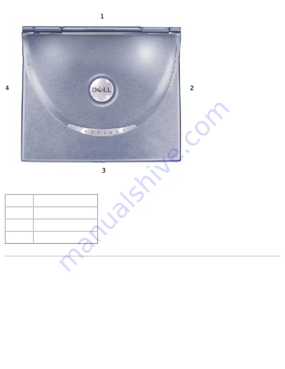
1

back

2

right

3

front

4

left

Screw Identification

When you are removing and replacing components, photocopy the place mat as a tool 

to lay out and keep track of the screws. The place mat provides the number of screws 

and their sizes.

file:///F|/Service%20Manuals/Dell/Inspiron/4150/begin.htm (3 of 6) [2/28/2004 7:29:39 AM]

Содержание Inspiron 4150

Страница 1: ...elp protect your computer from damage and ensure your own personal safety Hints Notices and Cautions HINT A HINT indicates important information that helps you make better use of your computer NOTICE A NOTICE indicates either potential damage to hardware or loss of data and tells you how to avoid the problem CAUTION A CAUTION indicates a potential for property damage personal injury or death Abbre...

Страница 2: ...spiron 4150 Back to Contents Page A Tour of Your Computer Dell Inspiron 4150 Front View Left Side View Right Side View Back View Bottom View Front View file F Service 20Manuals Dell Inspiron 4150 tour htm 1 of 14 2 28 2004 7 28 05 AM ...

Страница 3: ... Lights The green lights located above the keyboard indicate the following Turns on when the numeric keypad is enabled Turns on when the caps lock function is enabled Turns on when the scroll lock function is enabled file F Service 20Manuals Dell Inspiron 4150 tour htm 2 of 14 2 28 2004 7 28 05 AM ...

Страница 4: ...block push objects into or allow dust to accumulate in the air vents Do not store your computer in a low airflow environment such as a closed briefcase while it is running Restricting the airflow can damage the computer or cause a fire Microphone Allows you to record audio Device Status Lights Turns on when you turn on the computer Turns on when the computer reads or writes data NOTICE To avoid lo...

Страница 5: ...ged or the computer is turned off Flashing orange The battery charge is low Solid orange The battery charge is critically low Touch Pad Use the touch pad and touch pad buttons as you would use a mouse For more information see the Tell Me How help file see Accessing Help Module Bay You can install devices such as an optical drive or the Dell TravelLite module in the module bay Display Latch Button ...

Страница 6: ...Help Power Button Press the power button to turn on the computer or to enter or exit a power management mode If the computer stops responding press and hold the power button until the computer turns off completely which may take about 4 seconds NOTICE Turn off your computer by performing a Windows shutdown Otherwise you may lose data Dell AccessDirect Button Press this button to launch various res...

Страница 7: ...e Accessing Help Hard Drive Stores software and data Security Cable Slot Lets you attach a commercially available antitheft device to the computer Instructions for installing antitheft devices are usually included with the device NOTICE Before you buy an antitheft device ensure that it will work with the security cable slot file F Service 20Manuals Dell Inspiron 4150 tour htm 6 of 14 2 28 2004 7 2...

Страница 8: ...ss the volume control keyboard shortcuts to adjust the volume of the integrated speakers For more information see the Tell Me How help file see Accessing Help Right Side View file F Service 20Manuals Dell Inspiron 4150 tour htm 7 of 14 2 28 2004 7 28 05 AM ...

Страница 9: ...more information see the Tell Me How help file see Accessing Help Infrared Sensor The infrared sensor lets you transfer files from your computer to another infrared compatible device without using cable connections Audio Connectors Attach a microphone to the connector file F Service 20Manuals Dell Inspiron 4150 tour htm 8 of 14 2 28 2004 7 28 05 AM ...

Страница 10: ...l Help in the Tell Me How help file see Accessing Help Network Connector Connects the computer to a network The lights next to the connector indicate activity for both wired and wireless network communications For information on using the network adapter see the online network adapter documentation supplied with your computer To access device user s guides see Need Additional Help in the Tell Me H...

Страница 11: ...CAUTION Do not block push objects into or allow dust to accumulate in the air vents Do not store your computer in a low airflow environment such as a closed briefcase while it is running Restricting the airflow can damage the computer or cause a fire Back View NOTICE To avoid damaging the computer wait 5 seconds after turning off the computer before you disconnect an external device CAUTION Do not...

Страница 12: ...o connect the optional floppy drive directly to the parallel connector using the optional floppy drive cable Docking Connector HINT Docking devices may not be available in some countries Connects the optional docking device A docking device allows you to easily use external devices with your computer such as an external keyboard mouse and monitor See the documentation that came with your docking d...

Страница 13: ...r before attaching or removing a PS 2 compatible device If the device does not work install the device drivers from the floppy disk or CD that came with the device and restart the computer USB Connector Connects USB devices such as a mouse keyboard or printer Video Connector Connects an external monitor For more information see Using the Display in the Tell Me How help file see Accessing Help AC A...

Страница 14: ...er power connectors and power strips vary among countries Using an incompatible cable or improperly connecting the cable to the power strip or electrical outlet may cause fire or equipment damage NOTICE When you disconnect the AC adapter from the computer grasp the adapter cable connector not the cable itself and pull firmly but gently to avoid damaging the cable Bottom View file F Service 20Manua...

Страница 15: ...eleases Press a latch release to remove a device in the module or battery bay Memory Module Cover Protects the memory module s the optional Mini PCI card and the optional modem see Memory Modules Mini PCI Card and Modem Docking Device Latch Latches onto the docking device Back to Contents Page file F Service 20Manuals Dell Inspiron 4150 tour htm 14 of 14 2 28 2004 7 28 05 AM ...

Страница 16: ...al Keyboard Problems Unexpected Characters Drive Problems PC Card Problems Network Problems General Program Problems E Mail Problems If Your Computer Gets Wet If You Drop or Damage Your Computer Resolving Other Technical Problems Accessing Help To access the Tell Me How help file 1 Click the Start button and then click Help and Support 2 Click User and system guides and then click User s guides 3 ...

Страница 17: ...ing Help Check the power light When the power light is lit or blinking the computer has power If the light is blinking the computer is in standby mode press the power button to exit a standby mode If the light is off the computer is either in a power management mode or off press the power button to exit a power management mode or to turn on the computer Charge the battery The battery charge may be...

Страница 18: ...evice such as a lamp Check the AC adapter Check the AC adapter cable connections If the AC adapter has a light ensure that the light is on Connect the computer directly to an electrical outlet Bypass power protection devices power strips and the extension cable to verify that the computer turns on Eliminate possible interference Turn off nearby fans fluorescent lights halogen lamps or other applia...

Страница 19: ... in the floppy drive Remove the floppy disk and restart the computer Not enough memory or resources Exit some programs and try again You have too many programs open Close all windows and open the program that you want to use Operating system not found Contact Dell See your Owner s Manual for contact information A required DLL file was not found The program that you are trying to open is missing an...

Страница 20: ...d the display to turn off Try pressing the power button Check the battery If you are using a battery to power your computer the battery charge may be depleted Connect the computer to an electrical outlet using the AC adapter and turn on the computer Test the electrical outlet Ensure that the electrical outlet is working by testing it with another device such as a lamp Check the AC adapter Check th...

Страница 21: ...y from the computer or monitor If your external speaker system includes a subwoofer ensure that the subwoofer is at least 60 cm 2 ft away from the computer or external monitor Eliminate possible interference Turn off nearby fans fluorescent lights halogen lamps or other appliances Rotate the computer to face a different direction Eliminate sunlight glare which can cause poor picture quality Adjust...

Страница 22: ...ion Sound and Speaker Problems If you have a problem with integrated speakers Adjust the Windows volume control Double click the speaker icon in the lower right corner of your screen Ensure that the volume is turned up and that the sound is not muted Adjust the volume bass or treble controls to eliminate distortion Adjust the volume using keyboard shortcuts Press to disable mute or reenable the in...

Страница 23: ...icon in the lower right corner of your screen Ensure that the volume is turned up and that the sound is not muted Adjust the volume bass or treble controls to eliminate distortion Test the speakers Plug the speaker audio cable into the line out connector on the computer Ensure that the headphone volume control is turned up Play a music CD Run the speaker self test Some speaker systems have a self ...

Страница 24: ... the printer icon 4 Click Properties and then click the Ports tab Ensure that the Print to the following port s setting is LPT1 Printer Port Reinstall the printer driver See Reinstalling Drivers and Utilities Modem and Internet Connection Problems NOTICE Connect the modem to an analog telephone wall jack only Connecting the modem to a digital telephone network damages the modem NOTICE Modem and ne...

Страница 25: ...o the modem Check the telephone line Try using a different telephone line If you are using a line that is 3 m 10 ft or more in length try a shorter one Irregular dial tone If you have voice mail service you might hear an irregular dial tone when you have messages Contact your telephone company for instructions on restoring a dial tone Turn off call waiting catch phone See your telephone directory ...

Страница 26: ...ve responses the modem is operating properly Scanner Problems Check the power cable connection Ensure that the scanner power cable is firmly connected to a working electrical outlet and that the scanner is turned on Check the scanner cable connection Ensure that the scanner cable is firmly connected to the computer and to the scanner Unlock the scanner Ensure that your scanner is unlocked if it ha...

Страница 27: ...isconnect it and connect the mouse directly to the computer To verify that the problem is with the mouse check the touch pad 1 Shut down the computer 2 Disconnect the mouse 3 Turn on the computer 4 At the Windows desktop use the touch pad to move the cursor around select an icon and open it If the touch pad operates correctly the mouse may be defective Reinstall the touch pad driver See Reinstalli...

Страница 28: ...lick Notepad 4 Type some characters on the external keyboard and verify that they appear on the display If you cannot verify these steps you may have a defective external keyboard To verify that the problem is with the external keyboard check the integrated keyboard 1 Shut down the computer 2 Disconnect the external keyboard 3 Turn on the computer 4 From the Windows desktop click the Start button ...

Страница 29: ...drive Ensure that Windows recognizes the drive Click the Start button and click My Computer If the drive is not listed perform a full scan with your antivirus software to check for and remove viruses Viruses can sometimes prevent Windows from recognizing the drive Insert a bootable disk and restart the computer Verify that the light is blinking indicating normal operation Ensure that the disk is n...

Страница 30: ...3 Reinstall the drive 4 Turn on the computer Clean the drive See Cleaning Your Computer in the Tell Me How help file for instructions see Accessing Help If you cannot play a CD CD RW or DVD HINT Because of different worldwide file types not all DVD titles work in all DVD drives High speed CD drive vibration is normal and may cause noise This noise does not indicate a defect with the drive or the C...

Страница 31: ... right corner of your screen Ensure that the volume is turned up and that the sound is not muted Reinstall the drive 1 Save and close any open files exit any open programs and shut down the computer 2 Remove the drive 3 Reinstall the drive 4 Turn on the computer Clean the drive or disc See Cleaning Your Computer in the Tell Me How help file for instructions see Accessing Help If you cannot eject t...

Страница 32: ... creation software Exit all other open programs Exiting all other open programs before writing to the CD RW may alleviate the problem If you have problems with a hard drive Allow the computer to cool before turning it on A hot hard drive may prevent the operating system from starting Try allowing the computer to return to room temperature before turning it on Check the drive for errors 1 Click the...

Страница 33: ...f you have problems with a PC Card not provided by Dell Contact the PC Card manufacturer Network Problems Check the network cable connector Ensure that the network cable connector is firmly connected to the connector on the computer and the network wall jack Check the network lights on the network connector Green indicates that the network connection is active If the status light is not green try ...

Страница 34: ...ation that may help you solve the problem Ensure that you properly installed and configured the program Reinstall the program if necessary A program stops responding End the program 1 Simultaneously press 2 Click the Applications tab and then select the program that is no longer responding 3 Click End Task If the computer does not respond to a keystroke or a proper shutdown press the power button ...

Страница 35: ...C power at the circuit breaker before attempting to remove the power cables from the electrical outlet Use the utmost caution when removing wet cables from a live power source 1 Shut down the computer disconnect the AC adapter from the computer and then disconnect the AC adapter from the electrical outlet 2 Turn off any attached external devices and disconnect them from their power sources and the...

Страница 36: ... of the metal connectors on the back of the computer 11 Replace the memory module s the memory module cover and the screw s 12 Replace the hard drive 13 Replace the module bay device and any PC Cards you removed 14 Replace the battery 15 Turn on the computer and verify that it is working properly HINT See Limited Warranties and Return Policy in your Owner s Manual for information on your warranty ...

Страница 37: ...uestions See Dell Technical Support Policy U S Only in your Owner s Manual for a description of the hardware and software support provided by Dell E mail Dell Go to support dell com and then click E Mail Dell in the Communicate list Send an e mail message to Dell about your problem you can expect to receive an e mail message from Dell within hours See Dell Technical Support Policy U S Only in your...

Страница 38: ...Solving Problems Dell Inspiron 4150 Back to Contents Page file F Service 20Manuals Dell Inspiron 4150 solving htm 23 of 23 2 28 2004 7 28 07 AM ...

Страница 39: ... such as wireless communications DVD drives and ZIP drives you may need the CD and documentation that came with those devices NOTICE The Dell Support website support dell com and the Drivers and Utilities CD provide approved drivers for Dell computers If you install drivers from other sources your computer might not work correctly To reinstall a driver or utility from your Drivers and Utilities CD...

Страница 40: ... utility that you want to install 6 Click the Install button if present to begin installing the driver or utility At the welcome screen follow the screen prompts to complete the installation If no Install button is present automatic installation is not an option For installation instructions either see the appropriate instructions in the following subsections or click Extract follow the extracting...

Страница 41: ...river appears click Next 11 Click Finish and restart your computer Using Microsoft Windows XP Device Driver Rollback If you install a new device driver that causes system instability you can use the Windows XP Device Driver Rollback utility to replace the new device driver with the previously installed version of the device driver If you cannot reinstall your previous driver by using the Device Dr...

Страница 42: ... other devices Conflicts are indicated by a yellow exclamation point beside the conflicting device or a red X if the device has been disabled 5 Double click any conflicting device listed to bring up the Properties window so that you can determine what needs to be reconfigured or removed from the Device Manager 6 Resolve these conflicts before checking specific devices 7 Double click the malfunctio...

Страница 43: ...your own checkpoints by creating restore points To limit the amount of hard disk space used older restore points will be automatically purged To resolve an operating system problem you can use System Restore from Safe Mode or Normal Mode to return your computer to an earlier operating state System Restore does not cause you to lose personal files stored in the My Documents folder data files or e m...

Страница 44: ...To use the System Restore Wizard click the Start button click Help and Support click System Restore and then follow the instructions in the System Restore Wizard window You can also create and name a restore point if you are logged on as the computer administrator or a user with administrator rights Manually Creating a Restore Point 1 Click the Start button point to All Programs Accessories System...

Страница 45: ...2 Ensure that Restore my computer to an earlier time is selected and click Next 3 Click a calendar date to which you want to restore your computer The Select a Restore Point screen provides a calendar that allows you to see and select restore points All calendar dates with available restore points appear in bold 4 Select a restore point and click Next If a calendar date has only one restore point ...

Страница 46: ...o not alter open or delete any files or programs until the system restoration is complete 1 Click the Start button point to All Programs Accessories System Tools and then click System Restore 2 Select Undo my last restoration and click Next 3 Click Next The System Restore screen appears and then the computer automatically restarts 4 After the computer restarts click OK Back to Contents Page file F...

Страница 47: ...stem unless instructed to do so by a Dell technical support representative 1 Insert the Operating System CD 2 Shut down the computer and then turn on the computer 3 Press any key when the Press any key to boot from CD message appears on the screen 4 When the Windows XP Setup screen appears press to select To set up Windows now 5 Read the information in the License Agreement window and then press o...

Страница 48: ... name for your computer when the Computer Name window appears and then click Next If you are reinstalling Windows XP Professional enter a name for your computer and a password when the Computer Name and Administrator Password window appears and then click Next 12 If you have a modem installed the Modem Dialing Information screen appears Enter the requested information and click Next 13 Enter the d...

Страница 49: ...ndows XP Operating System Dell Inspiron 4150 17 Reinstall the appropriate drivers 18 Reinstall your virus protection software Back to Contents Page file F Service 20Manuals Dell Inspiron 4150 windows htm 3 of 3 2 28 2004 7 28 09 AM ...

Страница 50: ...mputer user or are directed to do so by Dell technical support do not change the settings for this program Certain changes might make your computer work incorrectly Viewing the System Setup Screens 1 Turn on or restart your computer 2 When the Dell logo appears press immediately If you wait too long and the Windows logo appears continue to wait until you see the Windows desktop Then shut down your...

Страница 51: ...mputer appear less bright A box in the upper right corner of the screen displays help information for the currently highlighted option a box in the lower right corner displays information about the computer System setup key functions are listed across the bottom of the screen The screens display such information as System configuration Boot Order Boot start up configuration and docking device conf...

Страница 52: ...em To control the boot sequence you can select highlight devices by pressing the and keys and then enable or disable the device or change their order in the list To enable or disable a device highlight the item and press Enabled items appear as white and display a small triangle to the left disabled items appear blue or dimmed without a triangle To reorder a device in the list highlight the device...

Страница 53: ...oot the computer the normal boot order is restored HINT You can only boot start up your computer from a CD CD RW or DVD drive installed as a fixed optical drive You cannot boot from one of these modules installed in the module bay Changing Printer Modes Set the Parallel Mode option according to the type of printer or device connected to the parallel connector To determine the correct mode to use s...

Страница 54: ...Using the System Setup Program Dell Inspiron 4150 Back to Contents Page file F Service 20Manuals Dell Inspiron 4150 setup htm 5 of 5 2 28 2004 7 28 09 AM ...

Страница 55: ...y is largely determined by the number of times the battery is charged Place the computer in standby mode or hibernate mode when you leave the computer unattended for long periods of time To exit a power management mode press the power button Power Management Modes Standby Mode Standby mode conserves power by turning off the display and the hard drive after a predetermined period of inactivity a ti...

Страница 56: ...xit standby mode by pressing a key or touching the touch pad or track stick Hibernate Mode Hibernate mode conserves power by copying system data to a reserved area on the hard drive and then completely turning off the computer When the computer exits hibernate mode it returns to the same operating state it was in before entering hibernate mode NOTICE You cannot remove devices or undock your comput...

Страница 57: ...touch pad or track stick For more information on hibernate mode see the documentation that came with your operating system Power Options Properties To access the Microsoft Windows Power Options Properties window 1 Click the Start button and click Control Panel 2 Under Pick a category click Performance and Maintenance 3 Under or pick a Control Panel icon click Power Options Power Schemes Tab The Po...

Страница 58: ...management options see the Windows XP Help and Support Center see Accessing Help Alarms Tab HINT To enable audible alarms click each Alarm Action button and select Sound alarm The Low battery alarm and Critical battery alarm settings alert you with a message when the battery charge falls below a certain percentage When you receive your computer the Low battery alarm and Critical battery alarm chec...

Страница 59: ... Enter hibernate mode Shut down Windows and turn off the computer Choose no action None or Do nothing To program these functions click an option from the corresponding drop down menu and then click OK Hibernate Tab The Hibernate tab lets you enable hibernate mode by clicking the Enable hibernate support check box Back to Contents Page file F Service 20Manuals Dell Inspiron 4150 power htm 5 of 5 2 ...

Страница 60: ...e the problem yourself quickly without having to contact Dell for assistance If you are experienced with computers and know what component s you need to test simply select the appropriate diagnostic test group s or subtest s If you are unsure about how to begin diagnosing a problem see Starting the Dell Diagnostics and Advanced Testing Features of the Dell Diagnostics The Dell Diagnostics helps yo...

Страница 61: ...te testing when an adjustable error limit is reached Extensive online Help screens that describe the tests and how to run them Status messages that inform you whether test groups or subtests were completed successfully Error messages that appear if any problems are detected Starting the Dell Diagnostics The Dell Diagnostics are located on a hidden Diagnostic utility partition on your hard drive HI...

Страница 62: ...ing the Pre boot System Assessment write down the error code s and then contact Dell before continuing on to the Dell Diagnostics See your Owner s Manual for contact information If you receive a message stating that no Diagnostics utility partition has been found follow the instructions on the screen to run the Dell Diagnostics from your Drivers and Utilities CD If the Pre boot System Assessment c...

Страница 63: ...Information and Results Provides test results test errors version numbers of the subtests used by the Dell Diagnostics and additional help on the Dell Diagnostics Program Options Allows you to change the settings of the Dell Diagnostics Exit If the Dell Diagnostics are being run from the Diagnostics utility partition on the hard drive reboots the computer If the Dell Diagnostics are being run from...

Страница 64: ...d Testing screen is presented as follows On the left side of the screen the Device Groups area lists the diagnostic test groups in the order they will run if you select All from the Run tests menu category Press or to highlight a test group On the right side of the screen the Devices for Highlighted Group area lists the computer s currently detected hardware and some of the relevant settings Two l...

Страница 65: ... highlighted in the Device Groups area on the main menu screen It also provides reasoning for using some tests Device Describes the function and purpose of the highlighted device in the Device Groups area For example the following information appears when you select the Device Help category for Diskette in the Device Groups area Diskette Drive A The diskette disk drive device reads and writes data...

Страница 66: ...en you boot your computer from your Drivers and Utilities CD the diagnostics checks your system configuration information and displays it in the Device Groups area on the main screen The following sources supply this configuration information for the diagnostics The system configuration information settings stored in NVRAM that you selected while using the system setup program Identification tests...

Страница 67: ...to send outgoing information and where to look for incoming information Because your printer is a parallel communications device the computer recognizes the printer by its LPT1 address and identifies it as a parallel port You can test your printer connection in the Parallel Ports tests Back to Contents Page file F Service 20Manuals Dell Inspiron 4150 diag htm 8 of 8 2 28 2004 7 28 11 AM ...

Страница 68: ...AC Adapter Physical Environmental Microprocessor Microprocessor type Intel Mobile Pentium 4M microprocessor that runs at 1 6 1 7 1 9 or 2 0 GHz L1 cache 8KB internal L2 cache 512 KB on die External bus frequency 400 MHz System Information System chip set Intel 845MP Data bus width 64 bits DRAM bus width 64 bits Microprocessor address bus width 32 bits file F Service 20Manuals Dell Inspiron 4150 sp...

Страница 69: ...PCMCIA 16 bits CardBus 32 bits Memory Memory module connector two user accessible SODIMM sockets Memory module capacities 128 256 and 512 MB Memory type 266 MHz DDR SDRAM Standard memory 128 MB Maximum memory 1 GB Ports and Connectors Serial 9 pin connector 16550C compatible 16 byte buffer connector Parallel 25 hole connector unidirectional bidirectional or ECP Video 15 hole connector file F Servi...

Страница 70: ... Dell docking device S video TV out 7 pin mini DIN connector optional S video to composite video adapter cable Mini PCI Type IIIA Mini PCI card slot with Wi Fi 802 11b wireless support Modem RJ 11 port Network adapter RJ 45 port Communications Modem Type v 92 56K MDC Controller softmodem Interface internal AC 97 bus Network adapter 10 100 Ethernet LOM Video Video type 64 bit hardware accelerated D...

Страница 71: ...digital and digital to analog Interfaces Internal PCI bus AC 97 External microphone in connector stereo headphones speakers connector Speaker two 4 ohm speakers Internal speaker amplifier 1 0 W channel into 4 ohms Volume controls keyboard shortcuts program menus Display Type active matrix TFT XGA SXGA UXGA Dimensions Height 214 3 mm 8 4 inches Width 285 7 mm 11 3 inches Diagonal 357 1 mm 14 1 inch...

Страница 72: ...rizontal 40 Vertical 10 30 Pixel pitch 0 28 x 0 28 mm XGA 0 20 x 0 20 mm SXGA 0 18 x 0 18 mm UXGA Power Consumption Panel with backlight typical 6 5 W XGA 7 0 W SXGA 7 5 W UXGA Controls brightness can be controlled through keyboard shortcuts Keyboard Number of keys 87 U S and Canada 88 Europe 91 Japan Key travel 2 7 mm 0 3 0 11 inch 0 016 inch Key spacing 19 05 mm 0 3 mm 0 75 inch 0 012 inch Layou...

Страница 73: ...graphics table mode 250 count sec 100 gf Size protrudes 0 5 mm higher than surrounding keycaps Battery Type 8 cell smart lithium ion 4460 mAh Dimensions Depth 88 5 mm 3 48 inches Height 21 5 mm 0 83 inch Width 139 0 mm 5 47 inches Weight 0 43 kg 0 95 lb Voltage 14 8 VDC Charge time approximate Computer on 2 5 hours Computer off 1 hour file F Service 20Manuals Dell Inspiron 4150 specs htm 6 of 9 2 ...

Страница 74: ...emperature range Operating 0 to 35 C 32 to 95 F Storage 40 to 65 C 40 to 149 F AC Adapter Input voltage 90 264 VAC Input current maximum 1 5 A Input frequency 47 63 Hz Output current 3 5 A Output power 70 W Rated output voltage 20 VDC Dimensions Height 27 94 mm 1 1 inches Width 58 42 mm 2 3 inches Depth 130 80 mm 5 15 inches Weight with cables 0 4 kg 0 9 lb Temperature range Operating 0 to 35 C 32...

Страница 75: ...drive 2 6 kg 5 7 lb With CD drive 2 6 kg 5 8 lb Environmental Temperature range Operating 0 to 35 C 32 to 95 F Storage 40 to 65 C 40 to 149 F Relative humidity maximum Operating 10 to 90 noncondensing Storage 5 to 95 noncondensing Maximum vibration using a random vibration spectrum that simulates user environment Operating 0 9 GRMS Storage 1 3 GRMS file F Service 20Manuals Dell Inspiron 4150 specs...

Страница 76: ... head parked position and a 2 ms half sine pulse Operating 122 G Storage 163 G Altitude maximum Operating 15 2 to 3048 m 50 to 10 000 ft Storage 15 2 to 10 668 m 50 to 35 000 ft Back to Contents Page file F Service 20Manuals Dell Inspiron 4150 specs htm 9 of 9 2 28 2004 7 28 12 AM ...

Страница 77: ...Connector Docking Connector PS 2 Connector USB Connector Video Connector S Video TV Out Connector Port Locations 1 air intake 6 PS 2 connector 2 serial connector 7 USB connector 3 parallel connector 8 video connector 4 docking connector 9 AC adapter connector 5 air vent Serial Connector file F Service 20Manuals Dell Inspiron 4150 pinouts htm 1 of 10 2 28 2004 7 28 14 AM ...

Страница 78: ...r hardware you may need pin number and signal information for the serial connector Pin Signal I O Definition 1 DCD I Data carrier detect 2 RXDA I Receive data 3 TXDA O Transmit data 4 DTR O Data terminal ready 5 GND N A Signal ground 6 DSR I Data set ready 7 RTS O Request to send 8 CTS I Clear to send 9 RI I Ring indicator Shell N A N A Frame ground Parallel Connector Use the 25 hole parallel conn...

Страница 79: ...the computer s parallel connector and require the appropriate software drivers from the adapter s manufacturer If you reconfigure your hardware you may need pin number and signal information for the parallel connector Pin Signal I O Definition 1 STB I O Strobe 2 D0 I O Printer data bit 0 3 PD1 I O Printer data bit 1 4 PD2 I O Printer data bit 2 5 PD3 I O Printer data bit 3 6 PD4 I O Printer data b...

Страница 80: ...N A Frame ground Docking Connector Use this connector to attach your computer to the optional docking device Pin Signal Pin Signal Pin Signal Pin Signal 1 STRB 5V 51 HSYNC 101 VGA_GRN 151 GND 2 PD0 52 VSYNC 102 GND 152 CLK_SPCI 3 PD1 53 GND 103 VGA_RED 153 GND 4 PD2 54 DOCKED 104 GND 154 SAD0 5 PD3 55 USB_VD1 105 VGA_BLU 155 SAD1 file F Service 20Manuals Dell Inspiron 4150 pinouts htm 4 of 10 2 28...

Страница 81: ...67 GND 117 SSERR 167 SAD11 18 QPCIEN 68 12V 118 SPERR 168 SAD12 19 S1 6M_EN 69 AFD 119 SLOCK 169 GND 20 DFDD LPT 70 ERROR 120 SSTOP 170 SAD13 21 GND 71 ACK 121 GND 171 SAD14 22 NC 72 GND 122 SDEVSEL 172 SAD15 23 NC 73 INIT 123 STRDY 173 SAD16 24 D_ATCTLED 74 SLCT_IN 124 SIRDY 174 SC BE1 25 D_PWRLED 75 BUSY 125 SFRAME 175 SC BE2 26 DOCK_PWR_SRC 76 PE 126 SCLKRUN 176 GND 27 DOCK_PWR_SRC 77 SLCT 127 ...

Страница 82: ...ND 142 SMRT1 192 SAD29 43 DOCK_ DC_IN 93 DTR0 143 SWRDATA 193 SAD30 44 DOCK_ DC_IN 94 TXD0 144 SWGATE 194 SAD31 45 DOCK_ DC_IN 95 RXD0 145 SRDATA 195 GND 46 DOCK_ DC_IN 96 DCD0 146 SINDEX 196 NC 47 DOCK_ DC_IN 97 NC 147 GND 197 NC 48 DOCK_ DC_IN 98 5VSUS 148 NC 198 NC 49 GND 99 NC 149 5VALW 199 NC 50 LOW_PWR 100 NC 150 NC 200 GND PS 2 Connector Use the 6 hole miniature DIN PS 2 connector to attach...

Страница 83: ...eypad mouse supply voltage 5 EXK_MSCLK I O External keyboard keypad mouse clock 6 KBD_CLK I Keyboard clock Shell N A N A Chassis ground USB Connector Use the USB connector to attach one or more USB devices such as a mouse to the computer USB is a peripheral standard that enables automatic detection of USB compliant peripheral devices file F Service 20Manuals Dell Inspiron 4150 pinouts htm 7 of 10 ...

Страница 84: ...N A 3 Data N A 4 Ground Cable ground Video Connector Use the 15 pin video connector to attach an external monitor to the computer If the image does not appear on the monitor immediately press Pin Signal I O Definition file F Service 20Manuals Dell Inspiron 4150 pinouts htm 8 of 10 2 28 2004 7 28 14 AM ...

Страница 85: ...O 5 V power source for CRT 10 GND N A Signal ground 11 M SEN I Digital monitor sense monitor detect ID1 12 DDC_DATA I Monitor detect serial data 13 HSYNC O Horizontal synchronization 14 VSYNC O Vertical synchronization 15 DDC_CLK 1 Monitor Detect serial clock Shell N A N A Frame ground S Video TV Out Connector Use this connector to connect your computer to a television file F Service 20Manuals Del...

Страница 86: ...ctors Dell Inspiron 4150 S Video Pin Signal 1 GND 2 GND 3 DLUMA L 4 DCRMA L Composite Video Pin Signal 5 NC 6 DCMPS L 7 GND Back to Contents Page file F Service 20Manuals Dell Inspiron 4150 pinouts htm 10 of 10 2 28 2004 7 28 14 AM ...

Страница 87: ...Display Cover Inserts Hard Drive Memory Modules Mini PCI Card and Modem Keyboard Display Display Assembly Display Latch and Hinge Covers Palm Rest Microprocessor Thermal Cooling Assembly Microprocessor Hybrid Cooling Fan Reserve Battery Speakers System Board Battery and Module Bay Latches Back to Contents Page file F Service 20Manuals Dell Inspiron 4150 remove htm 2 28 2004 7 28 14 AM ...

Страница 88: ...t click the document title click Save Target As in Microsoft Internet Explorer or Save Link As in Netscape Navigator and specify a location on your hard drive Right click only the following link Getting Started sheet pdf 2 75 MB Dell Inspiron 4150 Owner s Manual pdf 2 34 MB Dell Inspiron 4150 Removing and Installing Parts pdf 657 KB HINT PDF files require Adobe Acrobat Reader which can be download...

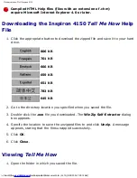
Страница 89: ...6 KB 659 KB 651 KB 783 KB 645 KB 2 Go to the directory location you specified when you saved the file 3 Double click the exe file you downloaded The WinZip Self Extractor dialog box appears 4 Specify the location to save the unzipped files to and click Unzip A message appears stating that the files unzipped successfully 5 Click OK 6 Click Close Viewing Tell Me How 1 Open the folder in which you sa...

Страница 90: ...Documentation Dell Inspiron 4150 2 Double click the filename Back to Contents Page file F Service 20Manuals Dell Inspiron 4150 document htm 3 of 3 2 28 2004 7 28 15 AM ...

Страница 91: ... avoid ESD ground yourself by using a wrist grounding strap or by touching an unpainted metal surface on the computer NOTICE Read Preparing to Work Inside the Computer before performing the following procedure 1 Remove the hard drive 2 Remove the keyboard 3 Remove the display 4 Remove the palm rest 5 Remove the microprocessor thermal cooling assembly 6 Remove the microprocessor 7 Remove the modem ...

Страница 92: ...2 M2 5 x 5 mm screws 9 10 Turn the computer over and remove the M2 5 x 5 mm screw which is labeled circle B with an arrow by the battery connector on the front center of the system board file F Service 20Manuals Dell Inspiron 4150 sysboard htm 2 of 4 2 28 2004 7 29 13 AM ...

Страница 93: ...tors away from the system board as you simultaneously lift the front of the system board out and away from the bottom case Replacing the System Board 1 Install the microprocessor on the replacement system board 2 Install the replacement system board a Insert the external microphone and headphone connectors through the file F Service 20Manuals Dell Inspiron 4150 sysboard htm 3 of 4 2 28 2004 7 29 1...

Страница 94: ...d or pinched when the complete assembly is put back together 4 Connect the right and left speaker assemblies that came with the new system board in the bottom case 5 Replace the palm rest the keyboard the display and the hard drive 6 Replace the module bay devices and any PC Cards or plastic blanks in the PC Card slot 7 Insert the CD that accompanied the replacement system board into the drive and...

Страница 95: ...er perform the following steps before you begin working inside the computer 1 Ensure that the work surface is clean to prevent scratching the computer cover 2 Save any work in progress and exit all open programs 3 Turn off the computer and all attached devices HINT Ensure that the computer is turned off and not in suspend mode or hibernate mode If you cannot shut down the computer using the comput...

Страница 96: ... battery is in use 11 Remove any device installed in the module bay 12 To dissipate any static electricity while you work use a wrist grounding strap or periodically touch an unpainted metal surface 13 Handle components and cards with care Do not touch the components or contacts on a card Hold a card by it edges or by its metal mounting bracket Hold a component such as a microprocessor by its edge...

Страница 97: ... Screw Identification When you are removing and replacing components photocopy the place mat as a tool to lay out and keep track of the screws The place mat provides the number of screws and their sizes file F Service 20Manuals Dell Inspiron 4150 begin htm 3 of 6 2 28 2004 7 29 39 AM ...

Страница 98: ...r and length Make sure that the screw is properly aligned with its corresponding hole and avoid over tightening Hard Drive Door 1 each Keyboard to Bottom Case 5 each Display Bezel 6 each Rubber Screw Covers 6 each Hinge Bracket to Bottom Case 5 each file F Service 20Manuals Dell Inspiron 4150 begin htm 4 of 6 2 28 2004 7 29 39 AM ...

Страница 99: ...y to Top Cover 5 each Display Feed Flex Cable 4 each Palm Rest to Bottom Case 5 each 3 each Hybrid Cooling Fan 2 each 1 each System Board to Bottom Case 10 each Modem to System Board 2 each file F Service 20Manuals Dell Inspiron 4150 begin htm 5 of 6 2 28 2004 7 29 39 AM ...

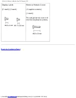
Страница 100: ...Inspiron 4150 Display Latch 2 each 2 each Memory Module Cover 2 captive screws 1 each The single screw is one of the five keyboard screws Back to Contents Page file F Service 20Manuals Dell Inspiron 4150 begin htm 6 of 6 2 28 2004 7 29 39 AM ...

Страница 101: ...rform repairs on your computer Damage due to servicing that is not authorized by Dell is not covered by your warranty NOTICE Unless otherwise noted each procedure in this manual assumes that a part can be installed by performing the removal procedure in reverse order file F Service 20Manuals Dell Inspiron 4150 system htm 1 of 2 2 28 2004 7 29 39 AM ...

Страница 102: ... cooling assembly 11 module bay device 4 hybrid cooling fan 12 main battery 5 microprocessor module 13 hard drive 6 system board 14 left speaker antenna assembly 7 right speaker antenna assembly 15 palm rest assembly 8 fan guard 16 keyboard Back to Contents Page file F Service 20Manuals Dell Inspiron 4150 system htm 2 of 2 2 28 2004 7 29 39 AM ...

Страница 103: ...documentation that came with your docking device for instructions 3 Keep the display open and tilt the computer back so that you can access the bottom of the computer 4 Slide and hold the latch release on the left side and remove any device installed in the module bay 5 Slide and hold the latch release on the right side and remove any battery installed in the battery bay 6 Locate the orange palm r...

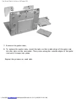
Страница 104: ... the palm rests insert the tabs on the inside edge of the palm rest into the slots on the computer Then press along the outside edges of the palm rest until it snaps into place Repeat the process on each side file F Service 20Manuals Dell Inspiron 4150 inserts htm 2 of 4 2 28 2004 7 29 40 AM ...

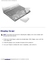
Страница 105: ...ded with the optional color inserts 1 Slide your index fingers under the straight edge of the display cover until the cover pops out 2 Slide the display cover towards the back of the computer 3 Use your fingers to release the cover completely and remove it file F Service 20Manuals Dell Inspiron 4150 inserts htm 3 of 4 2 28 2004 7 29 40 AM ...

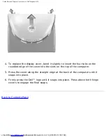
Страница 106: ...ver into the slots on the top of the computer 5 Press the cover along the straight edge at the back of the computer until it snaps into place 6 Firmly press the Dell logo until it snaps into place Press above both hinge covers to engage the final snaps Back to Contents Page file F Service 20Manuals Dell Inspiron 4150 inserts htm 4 of 4 2 28 2004 7 29 40 AM ...

Страница 107: ...eeze the top of the hard drive case and avoid dropping it NOTICE Read Preparing to Work Inside the Computer before performing the following procedure NOTICE To prevent data loss turn off your computer before removing the hard drive Do not remove the hard drive while the computer is running in standby mode or in hibernate mode 1 Save and close any open files exit any open programs and shut down the...

Страница 108: ...rive NOTICE Use firm and even pressure to slide the hard drive into place If you force the hard drive into place using excessive force you may damage the connector 1 Lift the hard drive door until you hear a click Push the hard drive into the drive bay until it is fully seated in the bay 2 Press the hard drive door down file F Service 20Manuals Dell Inspiron 4150 hdd htm 2 of 3 2 28 2004 7 29 40 A...

Страница 109: ...Hard Drive Dell Inspiron 4150 3 Replace the M3 x 5 mm screw in the hard drive door Back to Contents Page file F Service 20Manuals Dell Inspiron 4150 hdd htm 3 of 3 2 28 2004 7 29 40 AM ...

Страница 110: ...ound yourself by using a wrist grounding strap or by touching an unpainted metal surface on the computer NOTICE Read Preparing to Work Inside the Computer before performing the following procedure 1 Turn the computer over and release the two captive screws from the cover 2 Remove the M2 5 x 12 mm screw labeled circle K from the cover This screw is also one of the five keyboard screws 3 Place your ...

Страница 111: ...electrical outlets and remove any installed batteries NOTICE To avoid ESD ground yourself by using a wrist grounding strap or by touching an unpainted metal surface on the computer NOTICE Read Preparing to Work Inside the Computer before performing the following procedure 1 Remove the memory module cover file F Service 20Manuals Dell Inspiron 4150 upgrades htm 2 of 8 2 28 2004 7 29 41 AM ...

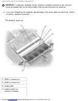
Страница 112: ...the inner metal tabs that secure the memory module 2 Use your fingertips to carefully spread apart the inner tabs on each end of the memory module connector The module pops up 1 JDIM 1 connector 2 JDIM 2 connector 3 keying tab 4 keying notch on memory module file F Service 20Manuals Dell Inspiron 4150 upgrades htm 3 of 8 2 28 2004 7 29 41 AM ...

Страница 113: ...the connector 2 Align the notch in the memory module edge connector with the keying tab in the connector on the system board 3 Slide the edge connector of the module firmly into the connector at a 45 degree angle and rotate the module down until you hear a click If you do not hear the click remove the module and reinstall it 4 Replace the cover and tighten the two captive screws Mini PCI Card You ...

Страница 114: ... performing the following procedure 1 Remove the memory module cover 2 Disconnect the Mini PCI card from any attached cables 3 Release the Mini PCI card by spreading the metal securing tabs until the card pops up slightly 4 Lift the Mini PCI card out of its connector NOTICE To avoid damaging the Mini PCI card never place cables on top of or under the card file F Service 20Manuals Dell Inspiron 415...

Страница 115: ...ables to the Mini PCI card 3 Replace the cover and tighten the screws Modem Removing the Modem NOTICE Disconnect the computer and any attached devices from electrical outlets and remove any installed batteries NOTICE To avoid ESD ground yourself by using a wrist grounding strap or by touching an unpainted metal surface on the computer NOTICE Read Preparing to Work Inside the Computer before perfor...

Страница 116: ...able 3 Pull straight up on the attached pull tab to lift the modem out of its connector on the system board and disconnect the modem cable 1 M2 x 3 mm screws 2 2 modem connector 3 modem cable 4 pull tab Replacing the Modem 1 Connect the modem cable to the modem file F Service 20Manuals Dell Inspiron 4150 upgrades htm 7 of 8 2 28 2004 7 29 41 AM ...

Страница 117: ...tem board and press down on the pull tab to seat the modem in the connector NOTICE Pressing down on the modem anywhere other than on the pull tab can break the modem 3 Install the two M2 x 3 mm screws that secure the modem to the system board 4 Replace the cover and tighten the screws Back to Contents Page file F Service 20Manuals Dell Inspiron 4150 upgrades htm 8 of 8 2 28 2004 7 29 41 AM ...

Страница 118: ...ies NOTICE To avoid ESD ground yourself by using a wrist grounding strap or by touching an unpainted metal surface on the computer NOTICE Read Preparing to Work Inside the Computer before performing the following procedure 1 Remove the hard drive 2 Turn the computer over and remove the five M2 5 x 12 mm screws labeled circle K file F Service 20Manuals Dell Inspiron 4150 keyboard htm 1 of 6 2 28 20...

Страница 119: ...replace Be careful when removing and handling the keyboard 4 Remove the center control cover a Use a small flat blade screwdriver or plastic scribe to lift the right edge of the center control cover and pry it loose from the bottom case b Lift the center control cover up and away from the bottom case file F Service 20Manuals Dell Inspiron 4150 keyboard htm 2 of 6 2 28 2004 7 29 42 AM ...

Страница 120: ...lease the keyboard from the palm rest use a small flat blade screwdriver or plastic scribe to pull up on the right edge of the blank key on the keyboard file F Service 20Manuals Dell Inspiron 4150 keyboard htm 3 of 6 2 28 2004 7 29 42 AM ...

Страница 121: ...se 7 Rotate the keyboard forward toward the front of the computer 8 Rest the key face of the keyboard on the palm rest NOTICE Do not pull on the keyboard flex and track stick cables 9 Pull up on the keyboard connector to disconnect it from the interface connector on the system board file F Service 20Manuals Dell Inspiron 4150 keyboard htm 4 of 6 2 28 2004 7 29 42 AM ...

Страница 122: ... on the system board The keyboard connector may have a label on it that shows the correct orientation of the keyboard connector to the system board interface connector 3 Carefully turn the keyboard over Align the keyboard boss support fit the left side of the keyboard into place and then snap the right side of the keyboard into place NOTICE Position the keyboard flex and track stick cables so that...

Страница 123: ...yboard Dell Inspiron 4150 6 Reinstall the five M2 5 x 12 mm screws in the holes labeled circle K Back to Contents Page file F Service 20Manuals Dell Inspiron 4150 keyboard htm 6 of 6 2 28 2004 7 29 42 AM ...

Страница 124: ... display before you remove the palm rest NOTICE Disconnect the computer and any attached devices from electrical outlets and remove any installed batteries NOTICE To avoid ESD ground yourself by using a wrist grounding strap or by touching an unpainted metal surface on the computer NOTICE Read Preparing to Work Inside the Computer before performing the following procedure file F Service 20Manuals ...

Страница 125: ...iron 4150 1 M2 x 3 mm screws 4 2 top cover 3 center control cover 4 M2 5 x 5 mm screws 5 5 bottom case 6 EMI shield bracket 1 Remove the hard drive 2 Remove the center control cover file F Service 20Manuals Dell Inspiron 4150 display htm 2 of 13 2 28 2004 7 29 44 AM ...

Страница 126: ... two M2 x 3 mm screws on the EMI shield bracket which is attached to the display feed flex cable 8 Remove the two M2 x 3 mm screws that secure the display feed flex cable to the system board NOTICE When reconnecting the display feed flex cable connector to the system board push down on the top left and top right ends of the connector Pressing on the center of the connector may damage resistors and...

Страница 127: ... tab that is attached to the display feed flex cable connector to remove the tab from the interface connector on the system board 10 Pivot the display up to a 90 degree angle and lift it up and out of the bottom case Display Assembly file F Service 20Manuals Dell Inspiron 4150 display htm 4 of 13 2 28 2004 7 29 44 AM ...

Страница 128: ...Covers Dell Inspiron 4150 1 rubber screw covers 4 5 M2 x 4 mm screws 5 2 M2 5 x 5 mm screws 4 6 display feed flex cable 3 display bezel 7 flex cable retention bracket file F Service 20Manuals Dell Inspiron 4150 display htm 5 of 13 2 28 2004 7 29 44 AM ...

Страница 129: ...covers out of the screw holes located on the front of the bezel 4 Remove the four M2 5 x 5 mm screws located on the front of the bezel NOTICE Carefully separate the bezel from the top cover to avoid damage to the bezel 5 Starting at the bottom of the display panel by the DELL logo use your fingers to separate the bezel from the top cover by lifting up the inside of the bezel while pushing in on th...

Страница 130: ... the display panel HINT If you have a Hitachi display panel remove the two M2 x 4 mm screws from the center of the left side of the display panel 6 Remove the M2 x 4 mm screw that secures the display feed flex cable to the display assembly through the black plastic flex cable retention bracket 7 Lift the display panel from the top and rotate the display panel out of the top cover 8 Disconnect the ...

Страница 131: ...connector 5 inverter connector 9 Remove the tape that secures the display panel connector and the tape that secures the middle of the display feed flex cable to the display panel 10 Pull the top flex cable connector down and away to remove it from the display panel connector file F Service 20Manuals Dell Inspiron 4150 display htm 8 of 13 2 28 2004 7 29 44 AM ...

Страница 132: ...anel in the top cover 6 Reinstall the five M2 x 4 mm screws that secure the display panel to the top cover Display Latch NOTICE Disconnect the computer and any attached devices from electrical outlets and remove any installed batteries NOTICE To avoid ESD ground yourself by using a wrist grounding strap or by touching an unpainted metal surface on the computer Removing the Display Latch 1 Remove t...

Страница 133: ...isplay Latch 1 On XGA panels place the display latch on top of its screw holes and then place the bracket on top of the display latch aligning the bracket and display latch screw holes On SXGA and UXGA panels align the screw holes and place the display latch and attached bracket in the top cover file F Service 20Manuals Dell Inspiron 4150 display htm 10 of 13 2 28 2004 7 29 44 AM ...

Страница 134: ... secure the display latch and bracket to the top cover Hinge Covers Removing the Hinge Covers 1 Remove the display 2 Rotate the hinges forward at an angle of approximately 90 degrees to the front of the display 3 To remove the hinge covers slide them off the hinges file F Service 20Manuals Dell Inspiron 4150 display htm 11 of 13 2 28 2004 7 29 44 AM ...

Страница 135: ...e bottom case 2 Close the display 3 Snap the hinge covers in place over the hinges HINT The right plastic hinge cover label includes an R and the left plastic hinge cover label includes an L The hinge cover labels face the back of the computer file F Service 20Manuals Dell Inspiron 4150 display htm 12 of 13 2 28 2004 7 29 44 AM ...

Страница 136: ...splay Assembly Display Latch and Hinge Covers Dell Inspiron 4150 1 right hinge cover 2 left hinge cover Back to Contents Page file F Service 20Manuals Dell Inspiron 4150 display htm 13 of 13 2 28 2004 7 29 44 AM ...

Страница 137: ...tal surface on the computer NOTICE Read Preparing to Work Inside the Computer before performing the following procedure 1 Remove the hard drive 2 Remove the keyboard NOTICE You must remove the display before you remove the palm rest the display hinges pass through the back of the palm rest 3 Remove the display and hinge covers 4 Turn the computer over and remove the three M2 5 x 12 mm screws label...

Страница 138: ...2 x 3 mm screws that are located on the back edge of the bottom case underneath the display b Remove the M2 x 3 mm screw located underneath the keyboard on the right side of the bottom case next to the microprocessor thermal cooling assembly and opposite the S video TV out connector 7 Pull up on the pull tab that is attached to the palm rest flex cable connector to remove it from the interface con...

Страница 139: ...spiron 4150 1 M2 x 3 mm screws 3 2 palm rest 3 palm rest flex cable 4 bottom case 5 touch pad connector 6 back center of the palm rest file F Service 20Manuals Dell Inspiron 4150 palmrest htm 3 of 4 2 28 2004 7 29 45 AM ...

Страница 140: ... to the palm rest 8 Starting at the back center of the palm rest use your fingers to separate the palm rest from the bottom case by lifting the inside of the palm rest while pushing in on the outside Back to Contents Page file F Service 20Manuals Dell Inspiron 4150 palmrest htm 4 of 4 2 28 2004 7 29 45 AM ...

Страница 141: ...e any installed batteries NOTICE To avoid ESD ground yourself by using a wrist grounding strap or by touching an unpainted metal surface on the computer NOTICE Read Preparing to Work Inside the Computer before performing the following procedure 1 Remove the hard drive 2 Remove the keyboard 3 Loosen the four captive screws that secure the microprocessor thermal cooling assembly to the system board ...

Страница 142: ...ng assembly 4 recess in the EMI shield prying location 4 Insert a screwdriver into the recess in the EMI shield under the front left corner of the thermal cooling assembly and pry the assembly up and away from the system board Replacing the Microprocessor Thermal Cooling file F Service 20Manuals Dell Inspiron 4150 thermal htm 2 of 3 2 28 2004 7 29 46 AM ...

Страница 143: ...oling assembly that is compatible with the new microprocessor 1 Place the right side of the microprocessor thermal cooling assembly under the palm rest and lower the assembly onto the system board 2 Tighten the four captive screws labeled 1 through 4 in consecutive order Back to Contents Page file F Service 20Manuals Dell Inspiron 4150 thermal htm 3 of 3 2 28 2004 7 29 46 AM ...

Страница 144: ...he Computer before performing the following procedure NOTICE When replacing the microprocessor to ensure proper thermal operation always install a new thermal cooling assembly that is compatible with the new microprocessor NOTICE Do not touch the processor die Press and hold the microprocessor down on the substrate on which the die is mounted while turning the cam screw to prevent intermittent con...

Страница 145: ...am screw 1 Remove the hard drive 2 Remove the keyboard NOTICE To ensure maximum cooling for the microprocessor do not touch the heat transfer areas on the microprocessor thermal cooling assembly The oils in your skin reduce the heat transfer capability of the thermal pads file F Service 20Manuals Dell Inspiron 4150 cpu htm 2 of 5 2 28 2004 7 29 47 AM ...

Страница 146: ...ng the microprocessor module properly in the ZIF socket does not require force NOTICE A microprocessor module that is not properly seated can result in an intermittent connection or permanent damage to the microprocessor and ZIF socket 1 Align the pin 1 corner of the microprocessor module with the pin 1 corner of the ZIF socket and insert the microprocessor module HINT The pin 1 corner of the micr...

Страница 147: ...Install a new microprocessor thermal cooling assembly 4 Update the BIOS using a flash BIOS update program CD Flashing the BIOS To update the BIOS 1 Ensure that the AC adapter is plugged into an electrical outlet and that the main battery is installed in the battery bay 2 Turn on the computer and when the Dell logo appears press immediately If you wait too long and the Windows logo appears continue...

Страница 148: ...cessor Dell Inspiron 4150 The computer boots updates the BIOS and reboots 5 Remove the flash BIOS update CD Back to Contents Page file F Service 20Manuals Dell Inspiron 4150 cpu htm 5 of 5 2 28 2004 7 29 47 AM ...

Страница 149: ...ounding strap or by touching an unpainted metal surface on the computer NOTICE Read Preparing to Work Inside the Computer before performing the following procedure 1 Remove the hard drive 2 Remove the keyboard 3 Remove the display 4 Remove the palm rest 5 Remove the microprocessor thermal cooling assembly 6 Remove the two M2 5 x 5 mm screws and one M2 x 3 mm screw that secure the hybrid cooling fa...

Страница 150: ... connector and remove the hybrid cooling fan HINT The fan power cable is long and can be pulled out from under the EMI shield to provide access to the connector NOTICE Do not block the keyboard screw hole when reinstalling the fan Route the fan power cable under the spring fingers and behind the keyboard screw hole to prevent damage to the fan power cable Back to Contents Page file F Service 20Man...

Страница 151: ...Hybrid Cooling Fan Dell Inspiron 4150 file F Service 20Manuals Dell Inspiron 4150 fan htm 3 of 3 2 28 2004 7 29 47 AM ...

Страница 152: ...ed devices from electrical outlets and remove any installed batteries NOTICE To avoid ESD ground yourself by using a wrist grounding strap or by touching an unpainted metal surface on the computer NOTICE Read Preparing to Work Inside the Computer before performing the following procedure 1 Remove the hard drive 2 Remove the keyboard 3 Disconnect the reserve battery cable from the system board conn...

Страница 153: ...or 5 speaker cable 6 opening for reserve battery cable Replacing the Reserve Battery 1 Connect the reserve battery cable to the system board connector and then route the battery cable through the opening in the EMI shield to the battery tray file F Service 20Manuals Dell Inspiron 4150 rsrvbatt htm 2 of 3 2 28 2004 7 29 48 AM ...

Страница 154: ...e adhesive on the bottom of the reserve battery and press the battery into place in the battery tray 3 Update the BIOS using the flash BIOS update program CD Back to Contents Page file F Service 20Manuals Dell Inspiron 4150 rsrvbatt htm 3 of 3 2 28 2004 7 29 48 AM ...

Страница 155: ...y using a wrist grounding strap or by touching an unpainted metal surface on the computer NOTICE Read Preparing to Work Inside the Computer before performing the following procedure The speakers are located on the front left and front right sides of the bottom case Take note of the speaker and antenna wire routing so that you can replace them properly under their routing clips file F Service 20Man...

Страница 156: ...Speakers Dell Inspiron 4150 file F Service 20Manuals Dell Inspiron 4150 speakers htm 2 of 6 2 28 2004 7 29 49 AM ...

Страница 157: ...Speakers Dell Inspiron 4150 1 right speaker 2 palm rest screw post 3 bottom case holders 2 4 left speaker file F Service 20Manuals Dell Inspiron 4150 speakers htm 3 of 6 2 28 2004 7 29 49 AM ...

Страница 158: ...Speakers Dell Inspiron 4150 file F Service 20Manuals Dell Inspiron 4150 speakers htm 4 of 6 2 28 2004 7 29 49 AM ...

Страница 159: ...the speaker NOTICE Handle the speaker assemblies and speakers with care to avoid damaging the speaker cones 6 Remove the speaker assemblies by pulling them straight up and out of the bottom case 7 Remove the speakers from the holders by sliding the speakers out the bottom of the holders HINT The left speaker has an in line connector and its antenna cable is longer than the antenna cable of the rig...

Страница 160: ... front palm rest screw post NOTICE Ensure that the speaker wires are routed securely under their mounting clips 3 Slide the speaker assembly down into the bottom case Back to Contents Page file F Service 20Manuals Dell Inspiron 4150 speakers htm 6 of 6 2 28 2004 7 29 49 AM ...
Страница 161: ...ed metal surface on the computer NOTICE Read Preparing to Work Inside the Computer before performing the following procedure 1 Remove the hard drive 2 Remove the keyboard 3 Remove the display 4 Remove the palm rest 5 Remove the system board 6 Remove the latch button by using a plastic scribe to push on the snap tabs until the latch button is released from the bottom case To prevent the latch assem...

Страница 162: ...tch assembly 2 4 bottom case 9 wear rib 5 latch buttons 2 Replacing the Battery and Module Bay Latches 1 If you are replacing the upper latch assembly a Slide the spring onto the slider and reinstall the latch in the holding features on the inside of the bottom case file F Service 20Manuals Dell Inspiron 4150 baylatch htm 2 of 3 2 28 2004 7 29 50 AM ...

Страница 163: ...erly if the slider is oriented incorrectly 2 Snap in the new latch button from behind the bottom case making certain that the snap tabs are fully engaged in the latch To prevent the latch assembly from coming loose apply pressure to the latch and spring while installing the latch button 3 Ensure that the newly installed latch moves smoothly and freely when pushed and released Back to Contents Page...

Отзывы: