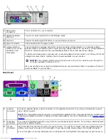
1
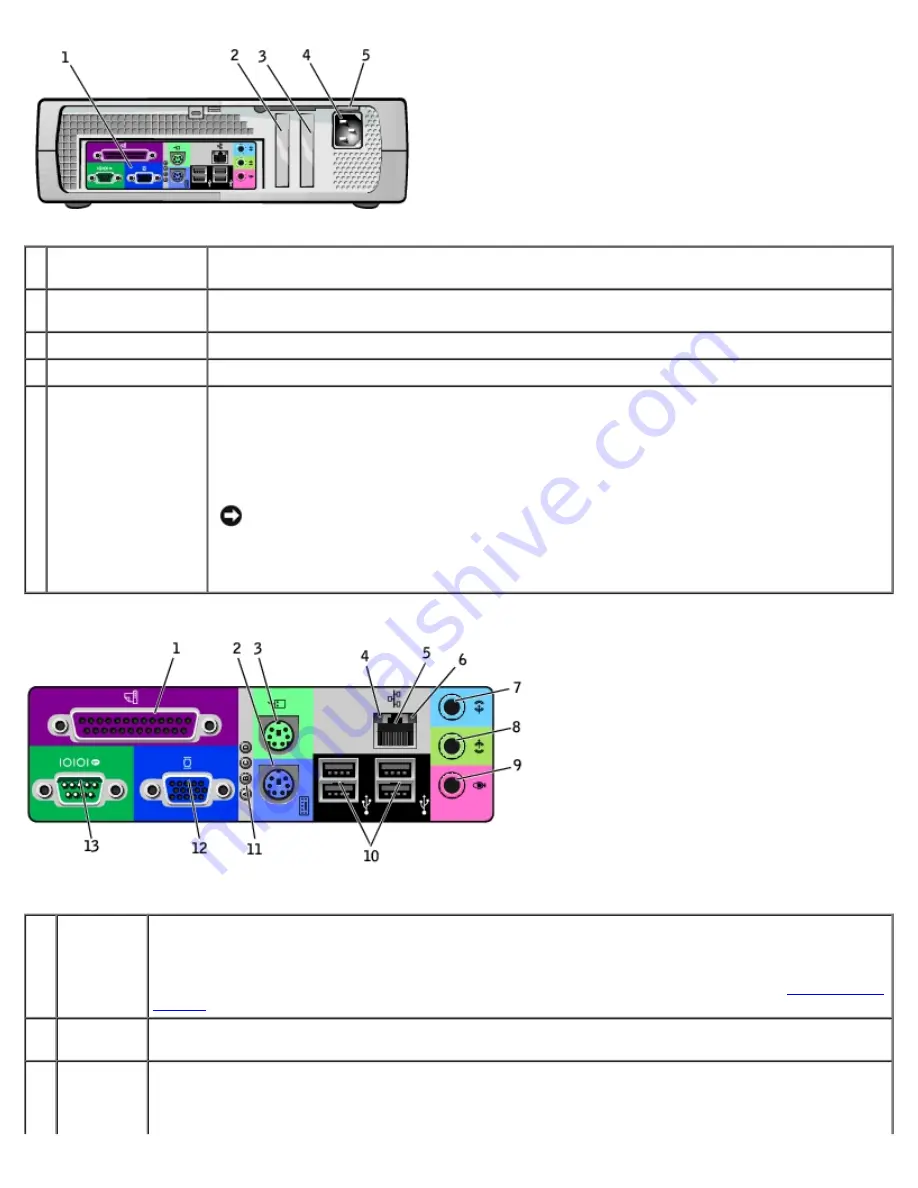
back-panel
connectors
The connectors for your computer.
2
AGP/DVI Adapter
card slot
The slot for half-height AGP or DVI Adapter cards.
3
card slot
The slot for half-height PCI cards or a second serial port card.
4
power connector
The connection for the power cable.
5
voltage selection
switch (may not be
available on all
computers)
Your computer is equipped with either an auto-sensing voltage selector or a manual voltage
selection switch. Computers with an auto-sensing voltage selector do not have a voltage selection
switch on the back panel and can automatically detect the correct operating voltage.
To help avoid damaging a computer with a manual voltage selection switch, set the switch for the
voltage that most closely matches the AC power available in your location.
NOTICE:
The voltage selection switch must be set to the 115-V position even though the
AC power available in Japan is 100 V.
Also, ensure that your monitor and attached devices are electrically rated to operate with the AC
power available in your location.
Back Panel
1
parallel
connector
Connect a parallel device, such as a printer, to the parallel connector. If you have a USB printer, plug it
into a USB connector.
NOTE:
The integrated parallel connector is automatically disabled if the computer detects an installed card
containing a parallel connector configured to the same address. For more information, see "
System Setup
Options
."
2
keyboard
connector
If you have a standard keyboard, plug it into the purple keyboard connector. If you have a USB keyboard,
plug it into a USB connector.
3
mouse
connector
Plug a standard mouse into the green mouse connector. Turn off the computer and any attached devices
before you connect a mouse to the computer. If you have a USB mouse, plug it into a USB connector.
If your computer is running Windows 2000 or Windows XP, Dell installed the necessary mouse drivers on
Содержание GX260 - Optiplex Pentium 4 2.0GHz 512MB 40GB CD
Страница 6: ......
Страница 29: ......
Страница 37: ...Back to Contents Page ...
Страница 40: ...information on resetting the chassis intrusion detector Back to Contents Page ...
Страница 73: ......
Страница 76: ......
Страница 86: ...2 padlock ring 3 two release buttons one on each side Back to Contents Page ...
Страница 111: ......
Страница 128: ...1 release buttons 2 security cable slot 3 padlock ring Back to Contents Page ...
Страница 149: ...13 Verify that your computer works correctly by running the Dell Diagnostics Back to Contents Page ...
Страница 155: ...Back to Contents Page ...
Страница 186: ...Back to Contents Page ...
Страница 210: ...Back to Contents Page ...
Страница 232: ...BSMI Notice Taiwan Only ...


