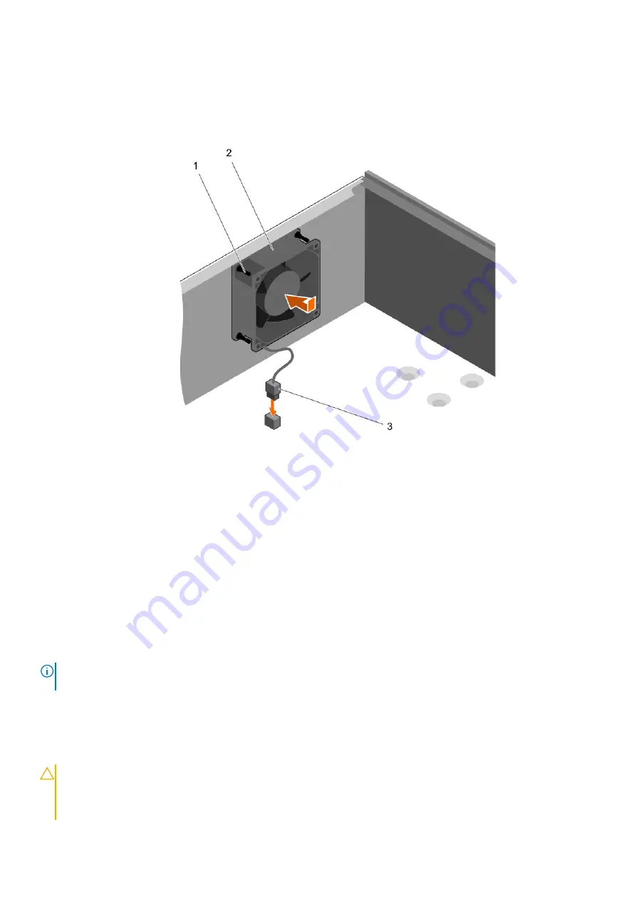
2. Align the four grommets on the chassis with the four holes on the sides of the cooling fan.
3. Pass the grommets through the corresponding holes on the cooling fan.
4. Stretch the grommets and slide the cooling fan toward the chassis until it locks into place.
5. Connect the cooling fan power cable to the connector on the system board.
Figure 37. Installing the cooling fan
a. grommets (4)
b. cooling fan
c. cooling fan power cable
Next steps
Follow the procedure listed in
After working inside your system
Internal USB memory key (optional)
A USB memory key installed inside your system can be used as a boot device, security key, or mass storage device. The USB connector
must be enabled by the
Internal USB Port
option in the
Integrated Devices
screen of System Setup.
To boot from the USB memory key, configure the USB memory key with a boot image and then specify the USB memory key in the boot
sequence in System Setup.
NOTE:
To locate the internal USB connector (INT_USB) on the system board, see
on page 104.
Replacing the optional internal USB memory key
Prerequisites
CAUTION:
Many repairs may only be done by a certified service technician. You should only perform troubleshooting and
simple repairs as authorized in your product documentation, or as directed by the online or telephone service and
support team. Damage due to servicing that is not authorized by Dell is not covered by your warranty. Read and follow
the safety instructions that are shipped with your product.
76
Installing and removing system components
Содержание E36S Series
Страница 2: ......
Страница 7: ...Contacting Dell EMC 119 Accessing system information by using QRL 119 Contents 7 ...
Страница 120: ...120 Getting help ...


