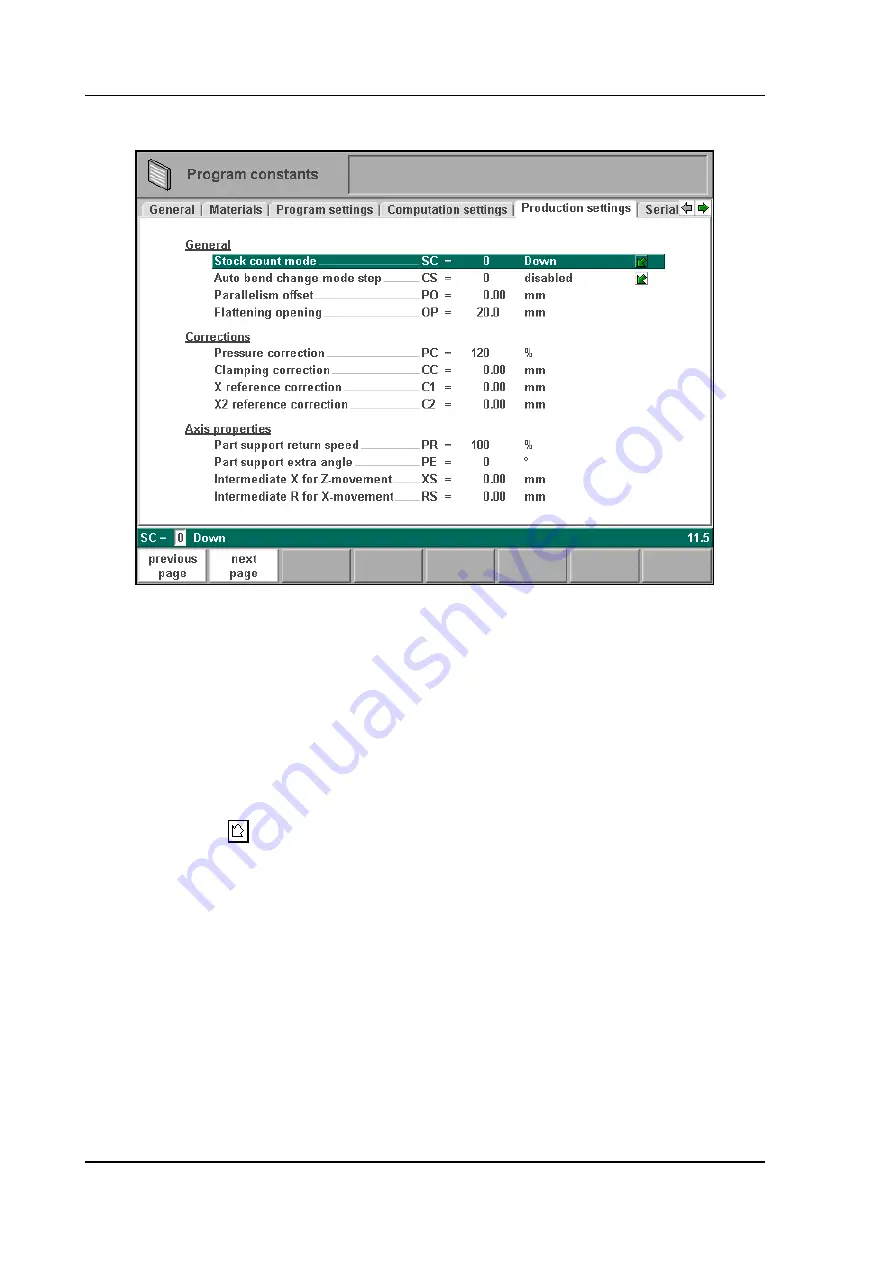
Delem DA-56 Скачать руководство пользователя страница 100

V0505, 7.10

7.6.

Production settings

7.h

Stock count mode . . . . . . . . . . . . . . . . . . . . . . . . . . . . . . . . . . . . . . . . . .

SC=

Setting for the stock counter in production mode, to have the stock counter (product 
counter) count up or down.
When downcounting is selected, the stock counter in production mode is decremented 
after each press cycle. When the counter has reached zero, the control is stopped. On the 
next start action, the stock counting value is reset to its original value.
When upcounting is selected, the counter is incrementd after each press cycle.
Downcounting can be useful if a pre-planned quota must be produced. Upcounting could 
be used to give a report on production progress.

Press the key 

 to select the required setting.

Auto bend change mode step  . . . . . . . . . . . . . . . . . . . . . . . . . . . . . . . .

CS = 

This parameter can be used to have automatic step change in the bending process with 
the "step by step"-mode. To be programmed 0 or 1.
When programmed 0:
No automatic step change (next bending parameters active) will take place. To perform 
the next bending you must select the new bending and press the start button.
When programmed 1:
The next bending parameters are loaded automatically but the axes will start positioning 
after the start button has been pressed.

Parallelism offset  . . . . . . . . . . . . . . . . . . . . . . . . . . . . . . . . . . . . . . . . . .

PO =

An overal parallelism, valid for the complete Y-axis stroke, can be programmed with this 
parameter. The programmed value will be checked against the maximum allowed value 

Содержание DA-56

Страница 1: ...Delem Manual version V0505 DA 56 Reference Manual Operation of Version V1...

Страница 2: ...ine Only authorised people should be able to create new or edit existing programs as well as pro gramming or editing of the tooldata Therefore the controller has a keyswitch to prevent uncontrolled pr...

Страница 3: ...ert an angle 2 5 2 3 Precision selection 2 5 2 4 Large Radius Bumping 2 7 2 5 Assignments 2 8 Parameter explanation 2 10 2 6 Bend sequence 2 11 Restoring a bend sequence 2 16 Minimum bending length 2...

Страница 4: ...per side and lower side 5 13 5 5 Saving loading of tools 5 16 6 Products and tools back up 6 1 6 1 Introduction 6 1 6 2 Directory navigation 6 2 6 3 Product backup 6 3 6 4 Tool back up 6 5 7 Program C...

Страница 5: ...Delem V0505 0 5 Corrections 9 4 Functions screen 9 6 Graphical visualisation 9 6 Zoomed values 9 7 Bumping correction 9 8 Manual positioning 9 9 9 2 Step mode 9 10 A Parameter index A 1...

Страница 6: ...V0505 0 6...

Страница 7: ...of all keys and their functions is given in the next section Beside the front panel keys a built in touchpad or external USB mouse can be used as a point ing device to select menu items parameters or...

Страница 8: ...ible to program all parameters of just one bending After pushing the start button all param eters are active and the backgauge will go into position It is also possible to move the axes manually Progr...

Страница 9: ...s of the following items Keyboard decimal point clear key Clearance of the input data field in the bottom left cor ner on the monitor screen 10 numerical keys 0 9 incl alphanumeric input plus minus to...

Страница 10: ...s Y backgauge axes End of menu program It is also possible to leave a menu by pressing ESC on an external keyboard or clicking with the mouse on the menu symbol in the upper left corner On the screen...

Страница 11: ...r the menu number and press ENTER use the arrow keys to scroll to the desired menu item and press ENTER click with the mouse once on the desired menu item Explanation of menu items Programming mode Se...

Страница 12: ...ite programs to or read programs from a back up medium 7 To program the dimensions of the upper tools 8 To program the dimensions of the under tools 9 To program the dimensions of the upper side of yo...

Страница 13: ...ity This help text is available when the question mark appears on the screen lower right corner 1 c To activate a help window for a parameter press the question mark key on the frontpanel or click wit...

Страница 14: ...ocated in a single window remove the window by pressing any key If there is a lot of text across multiple windows an arrow sign appears below the help symbol Use the left and right arrow keys or click...

Страница 15: ...on the control have a limited number of possible values Beside such parameters the sign appears This means that the key can be pressed to get a listbox with possible values of this parameter This list...

Страница 16: ...imum production time and manipulation possibilities of the product Features of the design tool Graphical design of product shapes in 2D Auto scaling Horizontal and vertical projected dimensions can be...

Страница 17: ...d to give directly multiples 45 degree angles e g Horizontal or vertical projections for 2D products After you entered the length of the line interval you can specify if this line interval is either t...

Страница 18: ...k directories or to export the finished product files to the required network directory 1 e Chapter 6 contains more information about networking possibilities 1 7 Software versions The version of the...

Страница 19: ...tands for version 2 is version number 1 is version level The version number is increased when new features are added to the software the level num ber is increased when minor corrections are needed in...

Страница 20: ...ormal operation or even when it fails to function according to its specifications 2 Delem provides the manual as is without warranty of any kind either expressed or implied including but not limited t...

Страница 21: ...y alphanum S6 If an existing product number is entered a warning appears that this product already exists You are asked whether to replace that existing product with the new product or not If you choo...

Страница 22: ...how to program materials Press the key to select the required setting Length L The Z length of the plate in millimeters mm Dimensions D1 Determine the use of the outside A or the inside B dimensions i...

Страница 23: ...value of the basic length of the product Then you enter the angle of the next side followed by the length of that side This procedure continues until the product has the desired profile A circle indic...

Страница 24: ...insert an angle depending on the drawing cursor position section 2 2 precision To define selected line segment with round cursor for high precision or if it is to be a closing dimension sec tion 2 3...

Страница 25: ...he line can be deleted 2 3 Precision selection When the drawing cursor small circle is on a line segment with S2 high precision or closing dimension can be selected With S2 these functions will be tog...

Страница 26: ...le directly placed between back stop and the centre of the die Notes Specifying line intervals with high precision and closing dimensions may result in longer pro duction time Also it will have priori...

Страница 27: ...ll need a smaller V die opening to be able to bend in a proper way Which value is acceptable as maximum for the V opening of the die is calculated and displayed on the screen For the definition of the...

Страница 28: ...essing Assignments results in the parameter pages If Variants programming is active indication Variants On in the title bar a warning is given that corrections will be lost Press Yes to proceed with t...

Страница 29: ...nts which have the most opti mal values to work within your surrounding This set can be stored into the internal memory by pressing softkey S4 save as default While programming another product you can...

Страница 30: ...length RF The computed inner radius is multiplied by this factor to correct the total developed length of the product The initial value of RF is 1 Radius factor X axis position AF The computed inner r...

Страница 31: ...segments Therefore the control can calculate an equal size for all segments This can be defined with this parameter 0 disabled no equal sizes 1 enabled equal sizes Press the key to select the require...

Страница 32: ...and 30 different punches One of each must be selected and can also be changed during the bending sequence determination These selections are prompted in the lower left corner of the screen Within the...

Страница 33: ...o possible without collision A complete overview of available softkeys in this screen is given on page 2 25 The function key MORE serves to switch between the primary and secondary row with function k...

Страница 34: ...necessary to produce the radius are computed during postpro cessing With this function key you can switch the collision protection check on or off This is indicated at the top of the screen When you...

Страница 35: ...al 4 and maximal 25 When a bendsequence has been determined a CNC program can be calculated and stored This process is called postprocessing When postprocessing is finished the blank length of the pro...

Страница 36: ...equired bends and press the swap button or press enter Then move the cursor to the bend with which it must be swapped and press the enter key or the swap button Now the bends have been swapped If for...

Страница 37: ...imum possible length you will get a warning message on the screen 2 r Machine Tool selection At each bend you can select one of the tools or machine shapes which are present in your library The displa...

Страница 38: ...available tools Which type of tools is shown depends on which type was prompted in the bend sequence screen punch die machine upper or lowerside Turn indication In the lower left corner a bend turn i...

Страница 39: ...al menu Function keys unbend next To unbend the graphical product bend pre vious To bend the graphical product shift gauge Select backgauge position swap Front to back turn of the product protection o...

Страница 40: ...sting corrections and bendsequence If such an existing program contains proper axis values and product positions then this informa tion can stay intact only the latest changes angle sheet length are r...

Страница 41: ...tions that may have been entered in one of the production modes These production modes are explained in chapter 10 When new S5 is chosen a new CNC program is calculated Corrections in the existing CNC...

Страница 42: ...ld corrections will be lost When No S5 is chosen the action is cancelled and Variants on remains The message CNC program and corrections will be lost is not literally true The CNC pro gram is still pr...

Страница 43: ...edit a program that is not currently loaded choose Product selection in the main menu In the offered list you have to select the wanted program number 3 a This page gives all data which are the same...

Страница 44: ...9 materials can be programmed on the control See the chapter about programming constants how to pro gram materials Press the key to select the required setting Blank length L The required length of th...

Страница 45: ...the direction which you want to execute in the first place You select the program of the product via menu 3 product selection 4 Go to menu 2 data editing Select the parameter CONNECT Enter the progra...

Страница 46: ...creen the function of the softkeys in the bottom row Function keys prev bend select previous bend next bend select next bend show library Open a window with an overview of the tool library From here a...

Страница 47: ...chine configuration Press the END button to leave this window Axis speeds Speed of the selected axis in the current bend Speed can be programmed in a percentage of the axis func tions axis functions t...

Страница 48: ...y to select a tool from the list Use the function key Show library to check the available tools Bendmethod BM Select the required bending method The control supports 4 methods Air bend Bottoming Flatt...

Страница 49: ...speed The value programmed here is the distance of the mute point above the plate By default the mute value from the programmed die is used Whether or not this parameter is present depends on machine...

Страница 50: ...osition for this specific bend The gauge position parameter GP you can program depends on the backgauge dimensions Backgauge dimensions are programmed in the menu program constants Default gauge posit...

Страница 51: ...ND you leave the window and the new values have been saved If you press cancel you leave the window without changes When you have changed the Gauge position then the axes positions in X and R direc ti...

Страница 52: ...e position when the beam moves in the opening direction with the Y axis beam waiting at the pinching point until the backgauge is at the retract posi tion 12 Step change at upper dead point with the Y...

Страница 53: ...ge during pressing auto calculated Dwell time T Holding time of punch at bending point Decomp speed BS The Back pressure speed is the programmable speed which is active during the pro grammed decompre...

Страница 54: ...bends in the bumping sequence should have the same angle number but a different bumping number Programming a radius bend in this manner will allow for bumping correction in the production mode 3 i Ba...

Страница 55: ...ation does not require a product drawing only these parameters must be programmed correctly Furthermore the parameter Blank Length must be programmed correctly in order to obtain a visualisation Note...

Страница 56: ...V0505 3 14 Example Product to make 3 k 0 to 5 are possible backgauge positions 1 to 4 are angle numbers 3 l Bend Angle AN Backgauge XN 1 1 0 2 4 5 3 3 1 4 2 1...

Страница 57: ...ursor on the parameter selected before 3 m A specific bend can be selected on the screen by putting the highlighted bar on that bend then pressing END The view is split in two parts At the top of the...

Страница 58: ...nsert a new bend between one of the bends select with the cursor keys first the bend after which a bend must be inserted Then push S1 for inserting results in a new bend which is a copy of the previou...

Страница 59: ...A bend is no longer marked when the mark is aborted when an action is finished or when this menu is left Ending data preparation data editing After pushing the END key in the Data edit screen a new p...

Страница 60: ...Decompression 3 Crowning device setting 4 Z axis position offset 5 X axis position correction Parameters 1 through 4 are only automatically recalculated if the parameter Auto computa tions edit see th...

Страница 61: ...or drawing number can be entered to select load a new program from the mainmemory The loaded product can directly be exe cuted in the automatic mode Each item in the list consists of a symbol and a n...

Страница 62: ...filter Function key to open a new button bar with extra function keys for product selection functions prod nr draw nr search local direc tory Via local directory you get an overview of the manually cr...

Страница 63: ...tton bar appears with addi tional softkeys 4 c Expanded directory 4 d Function keys prod nr Products are shown in columns with symbols and product number they are sorted on product number This is the...

Страница 64: ...can search for products with a certain number or name At the bottom of the screen the text search to load is displayed to indicate that you may enter a string the control will search for You can eith...

Страница 65: ...4 f Function keys make subdir Add a new subdirectory The name of the subdirectory can be any alpha numeric string of maximal 8 characters Avoid the use of slashes remove sub dir Delete a subdirectory...

Страница 66: ...the new name Subdirectories are called subdirectories because these directories reside under the local directory PRODUCTS 4 g It is not possible to copy products from one subdirectory to another subdi...

Страница 67: ...hes 5 2 1 The punch menu The programming of punches is started by choosing Punches in the main menu The punch profile can be created with help of the programming facilities of the control 5 a A listin...

Страница 68: ...sions as in the product drawing facilities Function keys previous page To select a previous page within the several pages of the punch library next page To select the next page within the several page...

Страница 69: ...of the tool automati cally change height To change the height dimension of the tool delete line To delete a line segment delete drawing To delete the complete tool from the library change data To chan...

Страница 70: ...ode C Alphanumeric tool name with a maximum of 20 characters Resistance R Maximum allowable force on punch in kN mm Length L Length of the punch to be used Z position Z Offset position of the middle p...

Страница 71: ...lready programmed Every time that this standard height is changed the flattening height will be made equal to this tool height due to safety reasons See figure 6 g The total toolheight will be used to...

Страница 72: ...gs head mounted and shoulder mounted 0 shoulder mounted default setting 1 head mounted Press the key to select the required setting 5 f If shoulder mounted is chosen the Y axis position is calculated...

Страница 73: ...ming of dies is started by choosing Bottom dies in the main menu 5 h A listing of the programmed dies is given A die can be selected with the highlighted cursor Function keys previous page To select a...

Страница 74: ...gle of the die Radius RA The radius of the edges of the V opening V die opening 5 i next page To select the next page within the several pages of the die library backup Save tools from library to disk...

Страница 75: ...he die is the backgauge position The mid position of the V opening will be placed on the centre line of the press brake shape 5 j The length of the flat section on the right hand side of the V grove w...

Страница 76: ...V in which FS flat section on the right hand side of the V grove V opening value In this formula also an extra small safety value has been added X safe turned negative ST This second safety value will...

Страница 77: ...te the speed change point mute and the flattening height will be used to calculate the end position of the Y axis beam to flatten the product The calculation will take 2x sheet thickness into account...

Страница 78: ...values are calculated each time the die drawing changes These 2nd values cannot be changed manually 5 n H2 is the height of the 2nd values H2 is not visible on the screen See for explanation upon the...

Страница 79: ...osition of the machine Before starting drawing the machine shape upper or lower side you must enter the press beam height of the upper part when the moving part of the upper side is in its mechanical...

Страница 80: ...after entering the height of the machine shape is the distance from the center line to the front side or the back side of the machine 5 p For the lower side of the machine the height is defined from...

Страница 81: ...Delem V0505 5 15 5 q...

Страница 82: ...ey save to disk has been pressed a screen like shown below should appear 5 r At the top of the screen the back up location is shown If this location is not correct you can change the subdirectory with...

Страница 83: ...tools if necessary 5 s You can make new subdirectories or delete existing ones with the softkeys make subdir and remove subdir If there are subdirectories present use the arrow keys to scroll to the r...

Страница 84: ...se of rename that a new toolnumber is proposed This new toolnumber is the first free tool number in the tool library Accept the proposed tool number with the enter key or enter the number of another f...

Страница 85: ...ing data are similar for all types of back up media floppy disk network or USB disk The actual back up directory consists of a device USB disk network and a directory The choice of devices depends on...

Страница 86: ...umber of times until the highest level is reached From there select the proper device and choose the correct subdirectory If a network connection is available you must first select network and subsequ...

Страница 87: ...ble It is also indicated to which loca tion a backup is made floppy disk network etc remove subdir Delete a subdirectory If the subdirectory is not empty the controller returns the message UNABLE TO R...

Страница 88: ...key backup directory or you should go to the program constants menu to change the device where products are saved to To save a product enter its number from the list and press enter Function keys all...

Страница 89: ...n 6 4 Tool back up To make a back up of tools to disk choose Tool backup in the main menu 6 e With this menu a back up of all programmed tools on the control is made punches dies and machine shapes Wh...

Страница 90: ...are imported Tools are linked to the control by their machine number When a restore operation is started the control will only import those tools which have the same machine number as the control If f...

Страница 91: ...ded across several pages They are discussed in the following sec tions 7 2 General 7 a Inch select 1 0 IS 1 dimensions in inches 0 dimensions in millimeters Press the key to select the required settin...

Страница 92: ...meters can be selected 7 2 It is also possible to continue on the next or previous page by using softkeys S2 c q S1 0 GB English 10 P Portugese 1 D German 11 PL Polish 2 DK Danish 12 LI Lithuanian 3 F...

Страница 93: ...control For each material three properties are present and can be viewed and edited Material name NA Name of the material The maximum allowed length of the material name is 25 charac ters the name mu...

Страница 94: ...r to the relevant line and press the function key delete material S4 to erase the values To program a new material move the cursor to an empty space and start programming its val ues 7 4 Program setti...

Страница 95: ...present in the database If corrections for certain bends are available then they will be offered On other occasions corrections can be interpolated and offered The correction database is adjusted by...

Страница 96: ...ce programming XX 0 angular format 1 projection method When you have two independent X axes X1 and X2 and the option OP X1X2 has been installed you can program the values for X1 X2 in a certain relati...

Страница 97: ...n chosen the name of that table if it has a name is shown on the screen Press the key to select the required setting Data preparation bend allowance BA 0 correction off 1 correction on With this param...

Страница 98: ...With this softkey the table can be modified to meet user requirements The table appears in a new window with its own set of function keys 7 f Each line contains a table entry with several parameters...

Страница 99: ...or an airbend multiplied by this factor in order to obtain the coin ing pressure Flattening offset OF The calculated depth position for the Y axis beam in case of flattening your product depends on th...

Страница 100: ...d be used to give a report on production progress Press the key to select the required setting Auto bend change mode step CS This parameter can be used to have automatic step change in the bending pro...

Страница 101: ...firm clamped plate it is possible to offset the calculated pinch point with the value here programmed A positive value will result in a deeper position a negative value in a higher position of the bea...

Страница 102: ...he Z axes are in position Old X axis position inside new position outside the zone backgauge starts along X axis Z movement is started when X axis is outside the zone Old X axis position as well as ne...

Страница 103: ...rial ports To change these settings contact your machine supplier The following settings are available DNC The serial port is used for DNC operation which means the control can be accessed by a comput...

Страница 104: ...ars There the finger dimensions can be pro grammed Default lay on position GD Default gauge lay on position when lay on is selected during the graphical bendsequence programming Default value 0 not la...

Страница 105: ...llowing parameters describe the dimensions of the backgauge and the lay on positions The number of parameters that has to be programmed depends on the number of gauge positions If more gauge positions...

Страница 106: ...ifferent finger levels Finger length FL The length of the first finger Gauge length L2 L3 The length of additional lay on levels 7 9 Maintenance 7 q Hours the number of hours the machine is running St...

Страница 107: ...bration 8 a All the parameters can be programmed independently of the programs in memory Manual mode By pushing this key the CNC is in manual mode Function keys view Button to select one out of three...

Страница 108: ...retract distance of available axes in the current bend This function is machine dependant and is described in detail in the chapter Data preparation manual pos Start the function to move axes manuall...

Страница 109: ...ickness TH Thickness of the plate in millimeters Length BL Length of the plate between the tools in millimeters Method BM Select the required bending method The control supports 4 methods Air bend Bot...

Страница 110: ...f the plate Auxiliary axis R If you have one or more auxiliary axes for instance a R axis Z axis or part support the parameters of these axes appear here When you have a R1 axis and a R2 axis the pro...

Страница 111: ...elism Y2 Difference of left and right hand side cylinder Y1 and Y2 When positive right hand side lower When negative right hand side higher The programmed value is active below the clamping point 8 c...

Страница 112: ...V0505 8 6 Zoom function When the function key zoomed values has been pressed the control switches to a new view with only axes values on the screen 8 d...

Страница 113: ...you wish to move Auxiliary axes With the handwheel the backgauge can be positioned manually This operation is only possible in Stop Manual Mode First you select the respective backgauge axis with hel...

Страница 114: ...teach an axis a correct position within the manual positioning mode When you have moved an axis to a certain position with the handwheel you may want to store this position To do so press the ENTER k...

Страница 115: ...is also indicated with a check tools warning message when you enter the automatic mode In the header information is displayed on the number of bends the repetition of a bend the product number the dr...

Страница 116: ...itional functions select rept no Switch between display of bend number or the number of repetitions of this bend all corr Open window to edit corrections of all bends of the product See section about...

Страница 117: ...of 92 degrees Then it is required to program Corr with 2 2 Programmed value of 90 degrees Measured value of 88 degrees Then it is required to program Corr with 2 In case the angle correction database...

Страница 118: ...Programmed value of 200 millimeters Measured value of 202 millimeters Then it is required to program Corr x with 2 2 Programmed value of 200 millimeters Measured value of 198 millimeters Then it is r...

Страница 119: ...ecessary correction to reach the programmed angle If there is already a correction present the control will adjust this correction to account for the latest discrepancy The column Stored correction is...

Страница 120: ...V0505 9 6 Functions screen 9 d Graphical visualisation 9 e...

Страница 121: ...Delem V0505 9 7 Zoomed values 9 f...

Страница 122: ...ich the correction can be entered 9 g When the general correction of an angle is altered all individual corrections are recalculated When any of the individual corrections is altered the general corre...

Страница 123: ...0505 9 9 Manual positioning In the automatic production mode it is possible to move the selected axis manually with the handwheel and change the axis positions with the teach function like in manual m...

Страница 124: ...pressing start on the front panel of the control 9 i After each bending step the control can stay in the current bend or jump to the next bend This depends on a parameter in the programming constants...

Страница 125: ...le 7 3 Equal sized bumping segments enabled 2 11 Finger height 7 15 Finger length 7 16 Finger width 7 15 Flattening height 5 11 Flattening height 5 5 Flattening offset 7 9 Flattening opening 7 11 Forc...

Страница 126: ...V opening 5 8 X1X2 difference programming 7 6 X2 reference correction 7 11 X allowance DIN 2 11 X Axis 8 4 X finger position 3 9 X reference correction 7 11 X safe 5 10 X safe turned negative 5 10 Y o...

Отзывы: