Operating the SA7x
2.1 SA7x Switches and Indicators
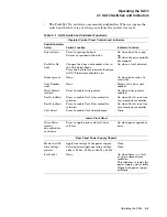
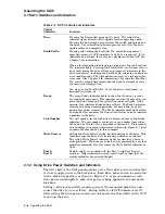
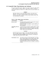
Table 2–2 OCP Controls and Indicators
Control
(Indicator)
Function
Run
Pressing the Run switch spins up the drive. The yellow Run
indicator lights after the drive spindle reaches operating speed.
Pressing the Run switch again releases the switch and spins down
the drive. The yellow Run indicator goes out only after the drive
spindle comes to a complete stop.
Fault/Set No.
Pressing and holding the Fault/Set No. switch during normal
operation causes all OCP indicators to light as a lamp test. If all
indicators do not light, there may be a problem with the OCP. See
Chapter 5 for information.
When a fault condition is detected in a disk drive, the red Fault/Set
No. indicator lights. Pressing the Fault/Set No. switch once after a
drive fault places the drive off line and causes all indicators in the
drive’s control set, including the Fault/Set No. indicator, to blink an
error condition code. The light pattern converts to a two-character
error code. (See Chapter 5 for information.) Pressing the Fault/Set
No. switch a second time commands the drive to attempt to clear
the error and return on line.
You also use the Fault/Set No. to set the drive unit number, as
described in Section 4.4.
Ready
The green Ready indicator lights to show that the drive is ready
for read/write operations. This indicator is activated only after you
press the Run switch and the yellow Run indicator lights. After
spin-up, this indicator blinks during self-test. The Ready indicator
remains on during normal operations, but may blink or go out
during heavy disk accesses. The Ready indicator must light within
60 seconds after you press the Run switch; failure to do so indicates
a problem in the drive.
Unit Number
The unit number for the disk drive is displayed next to the Ready
indicator. The unit number can be set to any number from either
000 to 255, or 000 to 999, as described in Section 4.4. Placement of
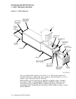
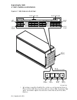
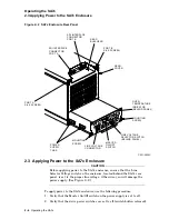
unit numbers in an actual installation is shown in Figure 2–1 (unit
numbers 000 through 003 in this example).
Write Protect
Setting the Write Protect switch disables writing to the drive. This
function keeps the drive data from being written over and lost.
The yellow Write Protect indicator lights to show that a drive is
write protected. The drive may also be write protected by a system
controller command; this also causes the Write Protect indicator to
light.
Port A
Port B
Ports A and B are enabled with the Port A and Port B select
switches. Yellow indicators in each switch light to show that the
system controller has selected the port.
2.1.2 Using Drive Power Switches and Indicators
The lower part of the front panel contains a set of four drive power switches that
you use to apply power to the disk drives. Each drive power switch is associated
with a disk drive position, as shown in Figure 2–1. A green indicator in each
drive power switch lights to show that power is being applied to the associated
disk drive.
Setting a drive power switch connects power to the associated disk drive and
causes the drive to run a self-test. During self-test, all OCP indicators are lit.
After setting the drive power switch, you must press the Run switch on the OCP
to spin up the drive.
2–4 Operating the SA7x

