DX8200
24
2
2.4.6 Outputs
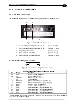
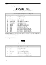
The relative signals are available on the
Output Signal connector
(Figure B, 3) and on the
25-pin I/O connector
(Figure B, 5).
Connector
Name
Function
25-pin
9-Pin
13
1
VS
power for external devices (positive pin)
1
2
GND
power for external devices (negative pin)
11
3
NO READ+
no read
3
4
NO READ-
no read output -
23
5
RIGHT+
right code
16
6
RIGHT-
right code output -
7
SPS+
slave presence
8
SPS-
slave presence sensor -
A 24 Vdc output voltage, is present between VS and GND. This may be used to power external
devices: electrical isolation between the scanner and external devices is lost in this case.
The
No Read
output activates when a code signaled by the presence sensor is not decoded.
The
Right
output is used to signal the presence of a right code, thus a good decode
condition.
All outputs are level or pulse programmable: a 50 ms pulse is generated in the second case.
Further programming information is supplied in the WinHost Help File.
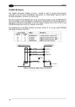
These outputs are created using optoisolated Darlington drivers and supply both the collector
and emitter in output, allowing both loads referenced to ground and to the power supply to be
driven.
The electrical features are given below:
Collector-emitter voltage
30 V Max.
Collector current
130 mA Max (pulsed).
Saturation voltage (VCE)
1 V at 10 mA Max.
Maximum power dissipation
90 mW at 50 °C (Ambient temperature).
DX8200 9-pin Connector
USER INTERFACE
NO READ+
RIGHT+
Vext
30 Vdc max
NO READ-
RIGHT-
3/5
4/6
Figure 28 - Output interface
When the load is powered by an external power supply, the voltage must be less than 30 V.
The limit requested by the maximum power dissipation is more important than that of the
maximum collector current: if one of these outputs is continuously driven, the maximum
current must not be more than 40 mA although 130 mA may be reached in pulse conditions.
Содержание DX8200
Страница 1: ...DX8200 Installation Manual ...
Страница 2: ......
Страница 3: ...DX8200 INSTALLATION MANUAL ...


