


INSTALLATION – DX8200 SERIAL INTERFACE
23
2
Signal
ENC+
ENC-
10
11
+ 5V
VS
A2
A1
GND
Ground
ENCODER
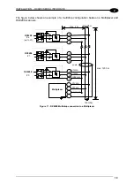
DX8200 Connector A and B
V
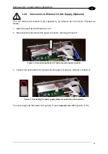
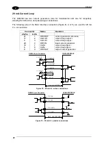
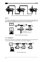
Figure 24 - Encoder NPN input command using DX8200 power
Signal
ENCODER
ENC+
ENC-
10
11
+ 5V
DX8200 Connector A and B
V
Vext
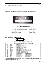
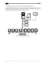
Figure 25 - Encoder NPN input command using external power
+
10
11
A2
A1
ENC+
ENC-
VS
GND
ENCODER
DX8200 Connector A and B
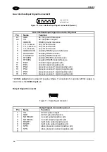
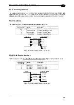
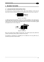
Figure 26 - Encoder PNP input command using DX8200 power
ENCODER
Signal
DX8200 Connector A and B
ENC+
ENC-
10
11
+ 5V
V
Vext
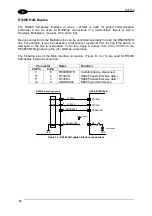
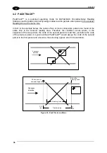
Figure 27 - Encoder PNP input command using external power
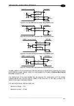
Isolation between the command logic and the scanner is maintained by powering the inputs
with a different supply voltage (Vext) from that supplied on the
Aux. Interface/Input Signal
A
and
B
connectors (VS).
The driving logic of the input signals may be powered, for convenience, with the voltage
supply between pins A2 (VS) and A1 (GND) of the connector. In this case, however, the
device is no longer electrically isolated.
The electrical features of these inputs are:
Maximum voltage
30 V
Maximum current
25 mA
Содержание DX8200
Страница 1: ...DX8200 Installation Manual ...
Страница 2: ......
Страница 3: ...DX8200 INSTALLATION MANUAL ...