DX8200
14
2
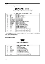
Main Interface Connector with I/O
Figure 13 - Main Interface connector with I/O
Main Interface Connector with I/O pinout
Pin
Name
Function
1
GND
ground reference
13
VS
24 Vdc power output
9
I.U.
(TXDEBUG)
only for service use
22
I.U.
(RXDEBUG)
only for service use
11
NO READ+
no read output (positive pin)
3
NO READ-
no read output (negative pin)
23
RIGHT+
right code output (positive pin)
16
RIGHT-
right code output (negative pin)
24
ENC+
encoder signal (positive pin)
15
ENC-
encoder signal (negative pin)
25
PS2+
presence sensor 2 signal (positive pin)
14
PS2-
presence sensor 2 signal (negative pin)
12
PS1+
presence sensor 1 signal (positive pin)
2
PS1-
presence sensor 1 signal (negative pin)
Pin
RS232
RS485
full-duplex
RS485
half-duplex
20 mA C.L.
21
DRVREF
17
TXD
TX485+
CLOUT+
5
RXD
TX485-
RTX485-
CLOUT-
20
DRVIN
19
GND
GNDRS485
GNDRS485
7
RS485CNTR
18
CTS
RX485+
CLIN+
6
RTS
RX485-
CLIN-
8
DRVOUT
Содержание DX8200
Страница 1: ...DX8200 Installation Manual ...
Страница 2: ......
Страница 3: ...DX8200 INSTALLATION MANUAL ...


