DX8200
16
2
RS232
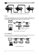
The main serial interface is used in this case for point-to-point connections; it handles
communication with the Host computer and allows both transmission of code data and
configuring the scanner.
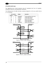
The following pins of the Main Interface connectors (Figure B, 4 or 5) are used for RS232
interface connection:
Connector
Name
Function
25-Pin
9-Pin
17
2
TXD
transmit data
5
3
RXD
receive data
19
5
GND
Ground
18
7
CTS
clear to send
6
8
RTS
request to send
It is always advisable to use shielded cables. The overall maximum cable length must be
less than 15 m (49.2 ft).
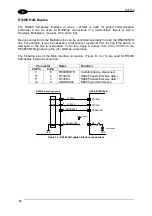
DX8200 9-pin Connector
USER INTERFACE
TXD
RXD
CTS
RTS
GND
RXD
TXD
GND
2
3
7
8
5
Earth
Ground
Figure 14 - RS232 connections
The RTS and CTS signals control data transmission and synchronize the connected devices.
If the RTS/CTS hardware protocol is enabled, the DX8200 activates the RTS output to
indicate a message can be transmitted. The receiving unit must activate the CTS input to
enable the transmission.
Содержание DX8200
Страница 1: ...DX8200 Installation Manual ...
Страница 2: ......
Страница 3: ...DX8200 INSTALLATION MANUAL ...


