BARCODE SCANNING FEATURES
223
5
5.7 REPLACING AN INSTALLED DS8110
If for any reason, a scanner fails, it can be replaced quickly with a spare unit with parameters
recovered from flash memory or a saved parameter file.
IMPORTANT:
This procedure assumes that system parameters have been
properly saved as described in sections 4.8.1, 5.2 and 5.3.
NOTE:
If you are not sure the replacement scanner has been defaulted to
factory settings, it is a good idea to default the unit before installing it in a
system. To do this:
1. Attach a power cable to the replacement scanner and apply
power.
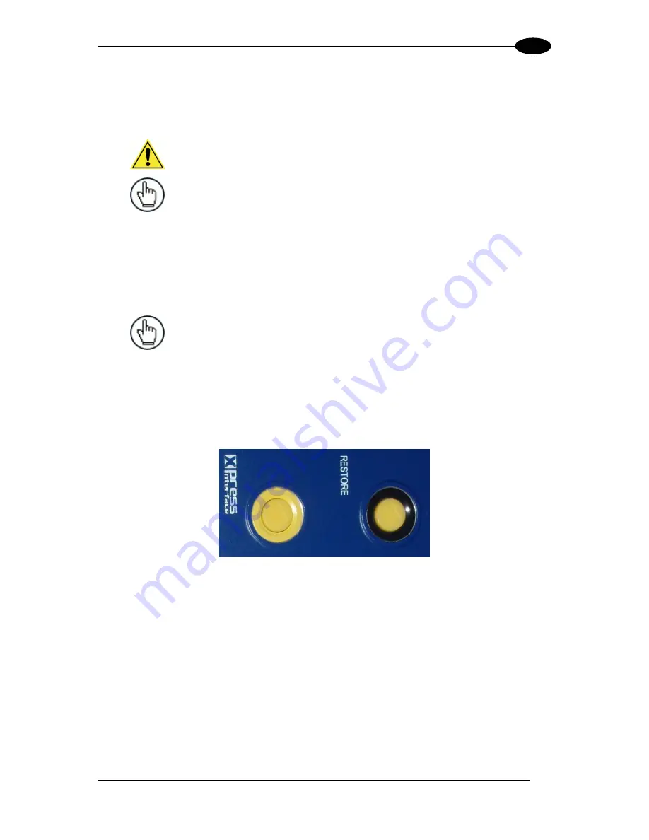
2. Simultaneously, press and hold down the yellow X-Press and
Restore buttons on the unit until the LEDs flash three times.
3. Release the buttons. The unit is now reset to the factory default.
NOTE:
If laser placement is critical (such as in Packtrack applications with
tight package spacing), the laser location must be marked on the conveyor
prior to the replacement, and these marks must be used to align the
replacement unit.
5.7.1 Replacing a Standalone Scanner Using Restore
A standalone scanner (a single scanner not connected to an array/tunnel) can be replaced
using the Restore button located near the LEDs on the top of the housing.
Figure 58: Restore Button
To replace the scanner using Restore:
1. Remove power from the existing scanner and remove the power and I/O cables.
2. Label the cables attached to ETH1 and/or ETH2 so you can easily identify where they
were connected, then remove the cables.
3. Detach the existing scanner from its mounting bracket, leaving the bracket attached to
the mounting structure.
4. Attach the replacement scanner to the mounting bracket.
5. Reattach the power, I/O, ETH1 and/or ETH2 cables.
Содержание DS8110
Страница 1: ...REFERENCE MANUAL DS8110 Barcode Scanner ...
Страница 40: ...DS8110 REFERENCE MANUAL 28 3 Figure 25 DS8110 Array Tunnel to SC5000 alternate with CBX ...
Страница 49: ...ELECTRICAL INSTALLATION 37 3 3 11 1 Photoelectric Sensor NPN Figure 32 Photoelectric Sensor Wiring NPN Output ...
Страница 50: ...DS8110 REFERENCE MANUAL 38 3 3 11 2 Photoelectric Sensor PNP Figure 33 Photoelectric Sensor Wiring PNP Output ...
Страница 52: ...DS8110 REFERENCE MANUAL 40 3 Figure 35 OEK 4 95B082050 Encoder Tachometer Wiring NPN Output ...
Страница 54: ...DS8110 REFERENCE MANUAL 42 3 Figure 37 OEK 4 95B082050 Encoder Tachometer Wiring PNP Output ...
Страница 56: ...DS8110 REFERENCE MANUAL 44 3 3 13 2 Powered Outputs Figure 40 Powered Outputs NPN PNP ...
Страница 248: ...DS8110 REFERENCE MANUAL 236 5 DS8110 2100 STANDARD RESOLUTION Figure 68 Reading Diagram DS8110 2100 Combined ...
Страница 249: ...BARCODE SCANNING FEATURES 237 5 Figure 69 Reading Diagram DS8110 2100 0 33mm 13mil ...
Страница 250: ...DS8110 REFERENCE MANUAL 238 5 Figure 70 Read Chart DS8110 2100 0 38mm 15mil ...
Страница 251: ...BARCODE SCANNING FEATURES 239 5 Figure 71 Read Chart DS8110 2100 0 50mm 20mil ...
Страница 252: ...DS8110 REFERENCE MANUAL 240 5 DS8110 2200 HIGH RESOLUTION Figure 72 Reading Diagram DS8110 2200 Model 2 Combined ...
Страница 253: ...BARCODE SCANNING FEATURES 241 5 Figure 73 Reading Diagram DS8110 2200 0 25mm 10mil ...
Страница 254: ...DS8110 REFERENCE MANUAL 242 5 Figure 74 Reading Diagram DS8110 2200 0 30mm 12mil ...
Страница 255: ...BARCODE SCANNING FEATURES 243 5 Figure 75 Reading Diagram DS8110 2200 0 33mm 13mil ...
Страница 256: ...DS8110 REFERENCE MANUAL 244 5 Figure 76 Reading Diagram DS8110 2200 0 38mm 15mil ...
Страница 257: ...BARCODE SCANNING FEATURES 245 5 DS8110 2300 LOW RESOLUTION Figure 77 Reading Diagram DS8110 2300 0 50mm 20mil ...
Страница 281: ......
Страница 282: ......


