background image

DS8110 REFERENCE MANUAL 


172 


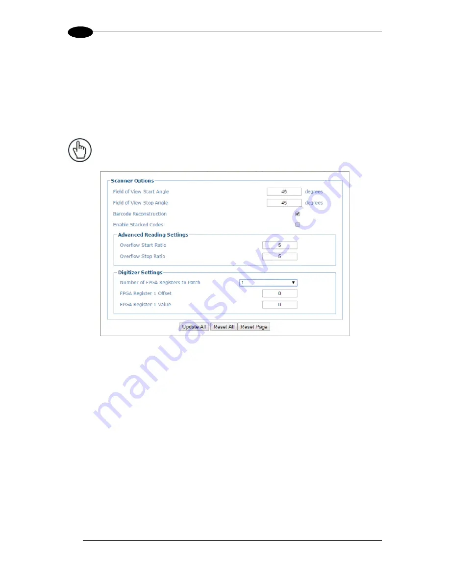
4.6.3  Device Settings | Device Name | Options 

 
Use  the 

Options

  window  to  configure  some  aspects  of  the  scanner  LEDs  and  X-Press 

interface.  
 

T

o view and edit the Options settings: 

 
1.  In the tree menu under 

Modify Settings

, navigate to 

Device Settings | Device Name (if 

applicable) | Options

. The 

Options

 window opens. 


NOTE:

 If more than one device is included in the scanning system, the 

device name will be listed in the menu tree after the Device Settings 
level.  


Содержание DS8110

Страница 1: ...REFERENCE MANUAL DS8110 Barcode Scanner ...

Страница 2: ...ss written consent from Datalogic S p A Datalogic and the Datalogic logo are registered trademarks of Datalogic S p A in many countries including the U S and the E U PackTrack ACR ASTRA and X PRESS are trademarks of Datalogic S p A or of Datalogic Group companies All other brand and product names are trademarks of their respective owners Datalogic shall not be liable for technical or editorial err...

Страница 3: ...8 1 8 2 Photocraft Encoder Tachometer Switch Setting 9 1 9 CBX Industrial Connection Box 10 1 10 SC5000 System Controller 11 2 MECHANICAL INSTALLATION 12 2 1 Preparing for Mechanical Installation 12 2 2 Unpacking Instructions 13 2 3 Installation Sequence 14 2 4 What You Need to Know About Your Application 15 2 5 Installation 16 2 5 1 Dimensions and Clearances 16 2 5 2 Physical Support Requirements...

Страница 4: ...48 4 1 Getting Started 48 4 1 1 Prerequisites 48 4 1 2 Starting e Genius 49 4 2 e Genius Basics 51 4 2 1 e Genius Menu Tree 51 4 2 2 Entering Text Using the Text Entry Tool 51 4 2 3 Update and Reset Buttons 52 4 2 4 Getting Help 52 4 3 Modify Settings 54 4 4 Modify Settings System Info 55 4 5 Modify Settings Global Settings 58 4 5 1 Modify Settings Global Settings Operating Mode 59 4 5 2 Modify Se...

Страница 5: ...Side Mounted Barcode Scanner Calibration Using PackTrack 213 5 6 4 Bottom Mounted Barcode Scanner Calibration Using PackTrack 220 5 6 5 Verifying PackTrack Calibration 221 5 7 Replacing an Installed DS8110 223 5 7 1 Replacing a Standalone Scanner Using Restore 223 5 7 2 Replacing a Slave Scanner in an Array Tunnel Automatically 224 5 7 3 Replacing a Slave Scanner in an Array Tunnel Using Restore 2...

Страница 6: ...Scanner Operation 251 6 2 7 Verify Photoelectric Sensor Operation 251 6 2 8 Verify Tachometer Operation 252 7 TROUBLESHOOTING 253 7 1 LED Diagnostic Indication 254 7 2 Error Codes and Resolutions 255 8 TECHNICAL FEATURES 261 8 1 Technical Specifications 261 GLOSSARY 264 INDEX 267 ...

Страница 7: ...lications Models Accessories and Downloads including documentation software drivers and utility programs SUPPORT SERVICES INDUSTRIAL AUTOMATION Several links from the Industrial Automation list take you to additional services such as Service Program which contains Maintenance Agreements and Warranty Extensions Repair Centers On Line RMA Return Material Authorizations Technical Support through emai...

Страница 8: ...s rotating above the threshold for its correct scanning speed WARNING Use of controls or adjustments or performance of procedures other than those specified herein may result in exposure to hazardous visible laser light BUREAU OF INDIAN STANDARD BIS WARNINGS OR CAUTIONS This symbol identifies a hazard or procedure that if incorrectly performed could cause personal injury or result in equipment dam...

Страница 9: ... classification Figure 1 Warning and Device Class Label Location Produit s conforme selon 21CFR 1040 10 sauf des dérogations relatives à la Laser Notice N 50 date Juin 24 2007 Dans le paquet il y a l étiquette s pour les pays où le texte d avertissement en français sont obligatoires Le s mettre sur le produit à la place de la version anglaise Figure 2 Exemple d étiquettes d avertissement laser ...

Страница 10: ...re inclusion of an adequate analysis and assessment of the risk s This evaluation was carried out in relation to the applicable points of the standards listed in the Declaration of Conformity Datalogic Automation products are mainly designed for integration purposes into more complex systems For this reason it is under the responsibility of the system integrator to do a new risk assessment regardi...

Страница 11: ... has been tested and found to comply with the limits for a Class A digital device pursuant to part 15 of the FCC Rules These limits are designed to provide reasonable protection against harmful interference when the equipment is operated in a commercial environment This equipment generates uses and can radiate radio frequency energy and if not installed and used in accordance with the instruction ...

Страница 12: ...xii GENERAL VIEW Figure 3 DS8110 Barcode Scanner Front and Left Side Views Figure 4 DS8110 Barcode Scanner Back and Right Side Views ...

Страница 13: ...t operating modes to suit the most various barcode reading system requirements Light source solid state laser diodes the light emitted has a wave length between 630 680 nm For laser safety precautions refer to the compliance section at the beginning of this manual 1 2 APPLICATIONS The DS8110 barcode scanners are specifically designed for industrial applications and for all cases requiring high rea...

Страница 14: ...m high density codes in a large reading area on very fast conveyors Flexibility The high frequency laser diode modulation system guarantees complete immunity to ambient light and allows installation of the DS8110 in any working area Reading parcels on conveyors As a result of the ASTRA multiple laser technology DX8210 and DS8110 give a great real time DOF even on high speed conveyors Furthermore D...

Страница 15: ...ersion Figure 5 Model Description Key 1 4 DS8110 VERSIONS DS8110 2100 Standard Resolution 932500001 DS8110 2200 High Resolution 932500002 DS8110 2300 Low Resolution 932500005 Model Description Part Number DS8110 X X X X Optic Version 0 Linear Optical Resolution 1 Standard resolution Communication Type 0 Standard version 2 High resolution Laser Number 2 Double laser 3 Low resolution ...

Страница 16: ... includes two external buttons that make up the X PRESS HMI interface and perform specific tasks without the need of connecting to e Genius See 5 5 for functional description Figure 6 DS8110 X PRESS Interface Buttons NOTE Some of these functions may be performed using e Genius See Chapter 4 ...

Страница 17: ...nner to the Host or Configuration PC 93A051348 REDs Cables ETH CABLE M12 M12 1M 90 90 SC5000 to SC5000 EBC ETH1 or ETH2 93A050087 REDS POWER ALARM CABLE 5M PWR 480B to CBX510 power alarm connections 93A050086 EBC Patch Cable ETH CABLE M12 M12 0 5M straight straight Female to Female EBC patch cable close the EBC when a scanner is sent to repair only for Master Slave 93A050085 Interface Cable SC5000...

Страница 18: ...93A251034 Power Supplies PG 100 K03 POWER SUPPLY 60W KIT US w M12 cable 93ACC0058 PG 100 K01 POWER SUPPLY 60W KIT EU w M12 cable 93ACC0059 PG 100 K02 POWER SUPPLY 60W KIT UK w M12 cable 93ACC0060 PG 240 K03 POWER SUPPLY 240W 8 Port M12 US w o M12 Cable 93ACC0144 PG 240 K01 POWER SUPPLY 240W 8 Port M12 EU w o M12 Cable 93ACC0145 PWR 480B POWER UNIT 110 230VAC 24V 93ACC0076 Sensors MEP 593 PHOTOCELL...

Страница 19: ...d distance from the sensor Without the photoelectric sensor the barcode scanner can be run in continuous mode See 4 5 1 Modify Settings Global Settings Operating Mode Depending on the application these devices may need to be configured differently While the photoelectric sensor and tachometer work well with belt conveyors a special configuration is needed for tilt tray and cross belt sorter applic...

Страница 20: ...The Encoder Step setting is entered in e Genius see section 4 5 1 Modify Settings Global Settings Operating Mode Encoder Step hundredths of millimeter Encoder Tachometer OEK 2 ENCOD KIT OEK 2 ENC KIT CAB 10m SPRING 93ACC1770 OEK 4 ENCOD KIT OEK 4 ENC KIT PNP 250PPR M12 M12 CABLE 95B082040 OEK 4 ENCOD KIT OEK 4 ENC KIT PNP 250PPR M12 FREE CABLE 95B082050 Encoder Model PPR Pulses Per Revolution PPI ...

Страница 21: ...raft OEK 2 Encoder Tachometer Switch Location Figure 10 Photocraft OEK 2 Encoder Tachometer Switch Settings NOTE Only switches 1 5 are used to set the PPR Pulses Per Revolution Switches 6 8 are used for PNP NPN settings as shown in the label on the arm of the encoder Cap Switch Access ...

Страница 22: ...up module which allows easy parameter restore and backup operations The backup module also provides an easy way to upload existing parameters to a replacement barcode scanner when necessary See section 3 9 1 for wiring options Figure 11 CBX510 Connection Box NOTE Scanner operation requires a CBX510 connection box or SC5000 controller Industrial Connection Box CBX510 Connection Box CBX510 for DS811...

Страница 23: ...210 scanners and its sturdy mechanical structure makes the SC5000 Controller the ideal solution for industrial environments The Controller allows connection to the Trigger and Encoder Tachometer PNP inputs are available via M12 circular connectors placed on the lower front panel see section 3 12 Figure 12 SC5000 System Controller System Controller SC5000 1000 System Controller Standard 935750001 S...

Страница 24: ... to perform any electrical installation procedures unless you are a trained technician IMPORTANT DS8110 barcode scanners contain electronics that may be affected by electrostatic discharge ESD To prevent personal injury or damage to the unit please follow the safety precautions and warnings found in the References section at the beginning of this manual Failure to follow these precautions may void...

Страница 25: ... that the DS8110 barcode scanners and all the parts supplied with the equipment are present and intact when opening the packaging the list of parts includes DS8110 reader L bracket Mounting screws two types and washers Barcode Test Chart Figure 13 Package contents ...

Страница 26: ...acket Mount the photoelectric sensor to the mounting structure optional Mount the tachometer to the mounting structure optional Mount the CBX connection box to the mounting structure Mount the SC5000 to the mounting structure Complete electrical installation See Chapter 3 Align the DS8110 for proper operation Configure the DS8110 See Chapter 4 Check DS8110 operations See Chapter 5 NOTE Everything ...

Страница 27: ... the conveyor width What is the conveyor speed Does conveyor speed vary or is it constant Product Specifications Are the packages being transported always singulated not touching or non singulated possibly touching How many different product sizes may be involved Are products justified toward away from reader centered or variable Application Specifications How will the barcode information be used ...

Страница 28: ...the barcode scanners see Chapter 8 Technical Features Multiple head systems may include further details on the physical support requirements with any application specific documentation provided 2 5 3 Vibration Limitations See Chapter 8 Technical Features IMPORTANT The DS8110 is a sealed unventilated unit Mounting the unit with 300mm 12 of clearance front top and sides is recommended for cooling an...

Страница 29: ...cation be sure to keep the following guidelines in mind All mounting structure assembly and equipment installation can be performed by one installer Determine the proper orientation and position of the barcode scanner Leave adequate clearances approximately 300 mm 12 inches for wiring Route wires carefully to reduce or minimize electrical noise When power and communication wiring must cross make t...

Страница 30: ...lowing capabilities It is adjustable enough for you to move your unit to the optimum position for proper scanning It allows a technician access to the barcode scanner while it is mounted It must be as vibration free as possible so as not to affect the scanning accuracy It is constructed of steel or aluminum It provides approximately 300 mm 12 inches minimum clearance on all sides This clearance is...

Страница 31: ... 12 screw holes M6 X 8 on the sides of the scanner for mounting The diagram below can be used for installation refer to reading diagrams See 5 10 and any application drawings for correct positioning of the scanner with respect to the reading zone and scanner orientation Figure 14 DS8110 mounting dimensions with L bracket ...

Страница 32: ...e 15 DS8110 mounting bracket assembly with countersunk screws In order to guarantee a laser line position tolerance of 1 5 cm 0 06 in tighten the two mounting screws a little at a time alternating between them and without applying torque to the scanner This allows the screws to seat properly into the countersunk holes Alternative Mounting Using Cap Screws and Washers Figure 16 DS8110 mounting brac...

Страница 33: ...ngles If the DS8110 needs to be mounted at a 5 degree angle or within 5 degrees of the angles shown in Figure 17 DS8110 mounting angles 5 25 or 35 degrees mount it to the opposite end of the L bracket as shown below Figure 18 DS8110 5 degree mounting option ...

Страница 34: ...labels at a variety of angles however significant angular distortion may degrade reading performance When mounting the scanners take into consideration these three ideal label position angles Pitch 0 Skew 0 to 45 and Tilt 0 Follow the suggestions for the best orientation Figure 19 Tilt Pitch and Skew Tilt Pitch Skew ...

Страница 35: ...cal installation details Most DS8110 applications are shipped with the CBX connection box and all the necessary cabling required to electrically install the system If your system requires custom length cables or other special wiring documentation specific to these requirements has been provided in your shipment This special documentation supersedes any contradictory content in this manual NOTE To ...

Страница 36: ...d the mounting structure to protective earth PE ground If used wire the photoelectric sensor or other trigger to the CBX510 connection box SC5000 Wire the tachometer to the CBX510 connection box SC5000 if used Wire serial ports to the CBX510 connection box SC5000 if needed Connect the M12 end of the Ethernet cable to the scanner s HOST port and network switch as required by your application Connec...

Страница 37: ...CTION BLOCK DIAGRAMS 3 3 1 Single DS8110 Barcode Scanner to CBX510 Figure 20 Single DS8110 to CBX510 NOTE The BM100 switches indicated below must be set to 0 zero and the connector indicated is not supported Figure 21 BM100 Backup Module in CBX510 ...

Страница 38: ...3 3 2 Master Slave Array with CBX510 Figure 22 Master Slave Array Tunnel with CBX510 NOTE The BM100 switches indicated below must be set to 0 zero and the connector indicated is not supported Figure 23 BM100 Backup Module in CBX510 ...

Страница 39: ...cenario if one scanner fails communication from the other scanners to the SC5000 Controller is not interrupted Figure 24 DS8110 Array Tunnel with SC5000 NOTE When using the SC5000 a Fieldbus Host only connects to the SC5000 Fieldbus model Profinet or Profibus at the connectors shown It cannot connect to the CBX An Ethernet Host connects to the HOST connector on the SC5000 top cover A Serial Host m...

Страница 40: ...DS8110 REFERENCE MANUAL 28 3 Figure 25 DS8110 Array Tunnel to SC5000 alternate with CBX ...

Страница 41: ...0mm 12 inches for wiring Route wires carefully to reduce or minimize electrical noise IMPORTANT When planning your installation wiring remember all power connections must be quick disconnect For PERMANENTLY CONNECTED EQUIPMENT a readily accessible disconnect device must be incorporated in the building installation wiring For PLUGGABLE EQUIPMENT the socket outlet must be installed near the equipmen...

Страница 42: ...ions to the scanner will include 1 I O Connects directly to the 25 pin D type connector on the CBX connection box NOTE The M12 I O connector Vcc pin is allowed a max sink current of 0 6A 2 POWER 3 ETH 2 Setup or EBC scanner network default IP Address 192 168 3 100 4 ETH 1 Host or EBC scanner network default IP Address 172 27 101 220 Figure 26 DS8110 Connector Panel Route wiring from the scanner s ...

Страница 43: ...nner and plug the RJ45 into the Ethernet port of your PC If the ETH 2 port is in use ETH 1 port can be used For information on connecting to e Genius see Chapter 4 NOTE ETH2 is the Setup port ETH1 is the HOST port NOTE A laptop can only communicate to a scanner that is connected to a CBX Connection Box or SC5000 Controller NOTE Parameters for tunnel are set up in MASTER scanner or SC5000 Controlle...

Страница 44: ...e to follow all safety procedures regarding high voltage as outlined in the Introduction to this manual No power should be applied to any device until all wiring is completed and checked for accuracy IMPORTANT The socket outlet must be installed near the scanner The outlet must be a readily accessible disconnect device GROUND Ground the scanner to safety ground protective earth ground PE See wirin...

Страница 45: ... separate power source to the CBX510 connection box The CBX510 receives its power through its connection to the DS8110 DX8210 Barcode Scanner Connecting a separate power source will be detrimental to the system operation IMPORTANT DISCONNECT POWER from the scanning system and CBX510 before wiring any components Loose lead cables must pass through the water tight seals in the base of the CBX510 con...

Страница 46: ... row 4 are used for RS232 interface connection Name Function SGND Signal ground isolated TX Transmit RTS Request to send RX Receive CTS Clear to send As suggested above the cable shield should be connected in the Shield position The RTS and CTS signals control data transmission and synchronize the connected devices If the RTS CTS hardware protocol is enabled the scanner activates the RTS output to...

Страница 47: ...he following positions of the CBX510 spring clamp connector row 4 are used for RS422 full duplex interface connection Name Function SGND Signal ground isolated TX RS422 output TX RS422 output RX RS422 input RX RS422 input Figure 30 RS422 Full Duplex Interface Connections Host CBX510 IMPORTANT For applications that do not use RS422 RX signals do not leave these lines floating but connect them to SG...

Страница 48: ... application uses a trigger other than the one specified by Datalogic follow the appropriate wiring diagram to assure proper wiring NOTE To confirm the photoelectric sensor is functioning properly watch the TRIG LED while the photoelectric sensor s beam is blocked The Datalogic photoelectric sensor also includes a status LED The following diagrams illustrate standard recommended wiring of the Phot...

Страница 49: ...ELECTRICAL INSTALLATION 37 3 3 11 1 Photoelectric Sensor NPN Figure 32 Photoelectric Sensor Wiring NPN Output ...

Страница 50: ...DS8110 REFERENCE MANUAL 38 3 3 11 2 Photoelectric Sensor PNP Figure 33 Photoelectric Sensor Wiring PNP Output ...

Страница 51: ...The following diagrams illustrate standard recommended wiring of an encoder to the CBX510 terminal block 3 12 1 Encoder Tachometer Wiring for NPN Output two models Figure 34 OEK 2 Encoder Tachometer Wiring NPN Output NOTE Some tachometers may have a different color coding V Red or White Orange Signal White or White Blue Ground Black or Orange White ...

Страница 52: ...DS8110 REFERENCE MANUAL 40 3 Figure 35 OEK 4 95B082050 Encoder Tachometer Wiring NPN Output ...

Страница 53: ...er Tachometer Wiring for PNP Output two models Figure 36 OEK 2 93ACC1770 Encoder Tachometer Wiring PNP Output NOTE Some tachometers may have a different color coding Red V or White Orange White signal or White Blue Black ground or Orange White ...

Страница 54: ...DS8110 REFERENCE MANUAL 42 3 Figure 37 OEK 4 95B082050 Encoder Tachometer Wiring PNP Output ...

Страница 55: ...t options including Complete Read Partial Read No Read Trigger On Trigger Off Multiple Read Right Match and Wrong No Match Schematics for Isolated and Non Isolated digital outputs are provided below 3 13 1 Unpowered Outputs Figure 39 Unpowered Outputs Outputs 1 3 Figure 38 OUTPUTS Block Maximum Voltage 30 V Collector Current pulse 130 mA Max Collector Current continuous 40 mA Max Saturation Voltag...

Страница 56: ...DS8110 REFERENCE MANUAL 44 3 3 13 2 Powered Outputs Figure 40 Powered Outputs NPN PNP ...

Страница 57: ...In most applications the cable connections to the scanner will include 1 CFG Configuration via laptop Ethernet cable 2 HOST 3 ETH 1 EBC scanner network 4 ETH 2 EBC scanner network 5 POWER 6 I O Connects directly to the 25 pin D type connector on the CBX connection box 7 ENC PNP Encoder Tachometer 8 TRG PNP Trigger Photoelectric Sensor 9 Water tight connectors0 Figure 41 SC5000 Bottom Panel Connect...

Страница 58: ...and photoelectric sensors are mounted is grounded to the conveyor or to the PE terminal inside the PWR 3 The Shield wires from the Encoder Tachometer and photoelectric sensor cables are connected to the proper Shield terminal in the CBX box 4 Normally steps 1 through 3 will guarantee proper function In case of problems such as transmission of strange or wrong characters devices stop working withou...

Страница 59: ...tion of your barcode scanner confirm that the barcode scanners CBX connection box and or SC5000 Controller have been properly installed mechanically and electrically Use the Installation Sequence at the beginning of this chapter and your application specifications to check your installation ...

Страница 60: ... parameters monitor read quality construct output messages and view diagnostics e Genius enables you to easily configure fine tune and monitor your scanner s operation e Genius provides ease of use for any operator level 4 1 1 Prerequisites Before setting up your barcode scanner you will need the following Computer Laptop Browser Internet Explorer 11 or later Firefox 30 or later Chrome 36 or later...

Страница 61: ...esults under Network and Sharing Center click View network connections c Right click Local Area Connection and then select Properties d Select the Networking tab Under This connection uses the following items click Internet Protocol Version 4 TCP IPv4 and then click Properties e Select Use the following IP address f In the IP address field type the first 3 octets of the IP address of the reader co...

Страница 62: ...he application enables all functions available to the user and displays the System Info window If the password is not valid the application displays a results box with the message Incorrect Password Click OK to return to the Log On window and enter the correct user name and password I you don t know the password contact your system manager 0 To log out of e Genius Click at the upper right corner o...

Страница 63: ... the folders to view any additional setup features 4 2 2 Entering Text Using the Text Entry Tool In cases where text needs to be entered to create message headers trailer custom messages or for other reasons the Text Entry Tool pencil icon will be displayed Click to open the Text Entry Tool You can enter text in the text field by typing or click on the character buttons to create your message Sele...

Страница 64: ... changes on the current page to their last saved values 4 2 4 Getting Help DS8110 DX8210 e Genius provides complete online help To access the complete help system Select Utilities Help in the e Genius menu tree The help Welcome window appears The Welcome page provides important product information as well as three ways to find specific help information Contents Index and Search To display contextu...

Страница 65: ...E GENIUS 53 4 2 Click the Show link in the upper left corner of the help window to access Contents Index and Search options 0 ...

Страница 66: ...L 54 4 4 3 MODIFY SETTINGS Use the Modify Settings Menu Tree selections during initial setup to configure your scanning system If necessary you can later make modifications to the configuration using the same menu selections ...

Страница 67: ...y Settings click System Info The System Info window opens 2 Enter the appropriate information in the form as described below Field Name Action Definition System Info System Description Enter a name to identify this scanning system in the text field Role Select Standalone or Master from the drop down list Standalone not controllers indicates a scan point with a single barcode scanner Master indicat...

Страница 68: ...ver Scanners Click Discover Scanners to automatically find all of the scanners in an array The discovered scanners will be listed in the Device Information portion of the window This step is only done during initial configuration and is not a troubleshooting option Distribute Software Click Distribute Software to send the current software residing on the master scanner to all of the slave scanners...

Страница 69: ...ction of the screen Click OK to add the selected device to the system Replace This is an option under the Edit drop down list in the Unconfigured Devices section of the screen When selected you can select from a list of slave scanners Those with a gray indicator meaning the unit is not connected in the system using MAC Address and Dev drop down lists Click OK to replace the selected scanner with t...

Страница 70: ...ections during initial setup to configure your DS8110 DX8210 Barcode Scanning System Global settings are applied to the system Master and then distributed by the Master Scanner to the Slave devices If necessary you can later make modifications to the global system settings using the same menu selections ...

Страница 71: ... that modes related parameters The three operating modes available are On Line Continuous and PackTrack and the available settings differ depending on the operating mode selected To edit the system Operating Mode 1 In the tree menu under Modify Settings navigate to Global Settings Operating Mode The Operating Mode window opens ...

Страница 72: ...quire and correctly decode the code If the operation is successful the barcode characters are transmitted on the serial interface or Ethernet input in the format defined by the current configuration and the right output event is raised at the end of the photoelectric sensor s active phase If a code cannot be decoded a no read message is sent and the no read event is raised at the end of the photoe...

Страница 73: ...or Stop from the drop down list When Start is selected the Timeout used to determine the reading phase will begin from the Start Input or Serial Start String normal operation When Stop is selected the Timeout used to determine the reading phase will begin from the Stop Input or Serial Stop String effectively extending the reading phase Verifier Settings Verifier Enable Select the check box to enab...

Страница 74: ... be sent in case of a mismatch wrong code read non valid code Beam Shutter Settings Beam Shutter Select Disabled Triggered or Enabled from the drop down list The Beam Shutter turns the laser off The Beam Shutter option can be used to increase the overall laser diode life when used in high ambient temperature applications over 35 C reduce power consumption and to turn off the laser for safety purpo...

Страница 75: ... Select Active Open or Active Closed from the drop down list to define the active state of the input Active Open The input is active when there is no current flowing through IN pins The input from the trigger source is normally closed The scanner goes into trigger mode when the input source is opened Active Closed The input is active when current flows through IN pins The input from the trigger so...

Страница 76: ...rammed Reading Phase Timeout expires If decoding is correct the data is transmitted on the serial port as defined by the configuration The output line selected for the right output event is activated and the relative message is transmitted on the serial interface or Ethernet input In case of a bad read a no read message is transmitted on the serial interface The output line selected for the no rea...

Страница 77: ...e the reading phase will begin from the Start Input or Serial Start String normal operation When Stop is selected the Timeout used to determine the reading phase will begin from the Stop Input or Serial Stop String effectively extending the reading phase Beam Shutter Settings Beam Shutter Select Disabled Triggered or Enabled from the drop down list The Beam Shutter turns the laser off The Beam Shu...

Страница 78: ...d by new code entries FIFO list depth exceeded Timeout A timeout measured in milliseconds is also applied to each code entry The current code entry will be flushed from the list when the timeout expires Encoder Steps a threshold measured in encoder steps is also applied to each code entry The current code entry will be flushed from the list when the number of encoder steps is exceeded Tx Line The ...

Страница 79: ...t Code Read Accepted xxx no codes in list A Yes Axx B Yes BAx B No BAx C Yes CBA D Yes DCB A Yes ADC A No Filter Number of Encoder Steps Enter a number of encoder steps from 1 to 15000 This parameter sets the number of Encoder Steps after which the FIFO First In First Out list entry is flushed Replicate same code when symbologies don t match Select the check box to enable a further code filter con...

Страница 80: ...oordinate code position the current code is discarded If not the current code is accepted and added to the list in the first position the remaining codes in the list are shifted If the list is full the oldest code in the list will be flushed Replicate same code when Z positions don t match Select the check box to enable a further code filter condition according to which a read code is added to the...

Страница 81: ...DL_OutputStruct Start Input Number Select an input from the drop down list to define the number of the input starting the reading phase Start Input Active Level Select Active Open or Active Closed from the drop down list to define the active state of the input Active Open The input is active when there is no current flowing through IN pins The input from the trigger source is normally closed The s...

Страница 82: ...photoelectric sensor to the TX Line transmit NOTE Tracking starts 10 cm 4 inches before and stops 10 cm 4 inches after the Reading Area in order to ensure the barcode is assigned to the correct package PS Line This parameter defines the read signal Y coordinate mm referred to the origin of co ordinates used for PackTrack configuration see below Example ...

Страница 83: ...ssigning the barcode for this reason With the Window Dimension parameter the Y coordinates that delimit the pack can be virtually extended to improve the assigning success rate see the following figure If the minimum distance between two consecutive packs is less than twice the value of the Window Dimension the window is dynamically resized dynamic window to half the distance between the two packs...

Страница 84: ...C reduce power consumption and to turn off the laser for safety purposes Disabled The laser is always on Triggered The laser is turned off as soon as the code s are read or when the reading phase ends The laser is turned on again when the next reading phase starts Enabled The laser is always off and all operations are suspended PackTrack Beam Shutter Timeout Select a time value from the drop down ...

Страница 85: ...below Field Name Action Definition Top Panel Displays a list of barcodes that have been added to the system with the following columns Idx Select an option button for the row barcode you wish to edit If a barcode type is displayed in the selected row its configuration can then be edited If a row displaying disabled is selected a barcode type can be selected and configured for that row Symbology Di...

Страница 86: ...String Rule Select Match or Do Not Match from the drop down list This parameter defines the matching rule according to which a code can be transmitted Match All codes matching the Pattern Match String will be transmitted Do Not Match All codes not matching the Pattern Match String will be transmitted Pattern Match String max 200 chars Click to activate the Text Entry Tool and create a pattern matc...

Страница 87: ...xample Code gT6k Match a code with 6 characters in any position having 12 as central characters Match String 12 Example Code datal12og35 The following is an example of a very complex string where and are used both as commands and as characters Match String 45 NUL AC NUL 251 Example Code GEN45 3iusdsAC 2516300 NOTE For Codabar codes the start stop characters must be considered in the match conditio...

Страница 88: ...ed Bar Count Select Variable or an available value from the drop down list The Bar Count allows to further specify the number of elements in the read code for Code 128 GS1 128 Code 93 ISBT 128 or Code 39 Full ASCII For these codes the same number of barcode elements bars spaces can be associated with a different number of characters Variable to select the correct number of characters set Label Len...

Страница 89: ...t Char Tx Select Disabled Lower Case or Upper Case from the drop down list This parameter is available only for Codabar code symbologies It allows transmitting the code start character Disabled The character is not selected Lower Case The character is transmitted in lower case Upper Case The character is transmitted in upper case Stop Char Tx Select Disabled Lower Case or Upper Case from the drop ...

Страница 90: ...he scanner stops decoding as soon as a code is read If the code is not read during the reading phase the No Read message is produced Standard Multi Label In Multi Label mode the barcodes selected up to 10 will all be read in the same reading phase If the reading phase terminates before all the codes are read a Global No Read message will be produced unless it is disabled in which case a Local No R...

Страница 91: ...oded Disable No Read Message The No Read Message is not transmitted Global No Read Message The No Read String will be sent if the scanner is unable to decode one or more barcodes in the reading phase Local No Read s Message Do not use this option when working in Single Label mode Use Global No Read String when No Codes Read Select the check box to allow the Global No Read String to be used if no c...

Страница 92: ...d contained in the following codes 00123456 12345600 12378456 The code 123456 is not considered contained in the following codes 12346507 string out of order 12345700 string not complete 120378456 or 0012345600 multiple blocks in the string Rule 2 the shorter code is not filtered by rule 1 In the longer code all possible sub strings of the same length as the shorter code string are compared with t...

Страница 93: ...his condition implicates that reading a code of the same type and length having very few different characters is probably a misread of the code itself and therefore the code read the least number of times should be ignored should not be considered as a multiple read of a different code This filter is based upon the following rules a multiple read condition occurs the two codes are of the same type...

Страница 94: ...save your text to the origin window text field or click Cancel to return to origin window without transferring text Strip Filter Collapse Select the check box to remove the stripped characters from the code and therefore reduce the code length collapsed It can even be null Replacement Char Click to activate the Text Entry Tool and enter the substitution character to replace all the stripped ones C...

Страница 95: ...he Code Combination drop down list the Barcode Configuration window reveals related input fields NOTE In case of Multi Label the codes will be distinguished EITHER by their symbology OR by their contents If two or more codes share the same symbology and content the scanner will perceive them as a unique code ...

Страница 96: ...the check box to allow the Global No Read String to be used if no codes at all are read This option is not available when Global No Read Message is selected from the No Read Message drop down list Global No Read String max 128 chars Click to activate the Text Entry Tool and create a string to be displayed when Global No Read Message is selected from the No Read Message drop down list Click Submit ...

Страница 97: ...Number of Different Characters field When checked this filter attempts to eliminate false multiple reads by determining if a short code read is contained in is a sub string of another longer code read This condition implicates that the short code is probably a misread of the same longer code and therefore should be ignored should not be considered as a multiple read of a different code This filter...

Страница 98: ...ase ends resulting in possible successive multiple read errors Max Number of Different Characters Enter a value from 0 to 5 in the field provided to define the maximum number of different characters allowed to still consider a code as being included in another one and therefore to be filtered If the number of different characters between the compared codes exceeds the value of this parameter the c...

Страница 99: ...his option was developed for the airports systems where there are often tall bar height codes and low bar height codes with the same content attached to baggage Travelers will often remove the large tall bar height code while leaving the smaller low bar height codes attached to the bag The next time they travel they may have multiple low bar height codes on their baggage plus the new tall bar heig...

Страница 100: ...erring text Strip Filter Collapse Select the check box to remove the stripped characters from the code and therefore reduce the code length collapsed It can even be null Replacement Char Click to activate the Text Entry Tool and enter the substitution character to replace all the stripped ones Click Submit to save your text to the origin window text field or click Cancel to return to origin window...

Страница 101: ...E GENIUS 89 4 Barcode Configuration Logical Combination When Logical Combination has been selected from the Code Combination drop down list the Barcode Configuration window reveals related input fields ...

Страница 102: ...ed code When editing the logical combination rule proceed as follows 1 Define the Barcode Settings indicating the type of expected code labels It is possible to define up to 10 different code types 2 Define how many code types groups are expected by editing the combination rule through the following logical operators Each group may include one or more selected code types AND operator which separat...

Страница 103: ...y is decoded the Multiple Read string is transmitted instead If the Multiple Read Message is disabled the third code label is ignored and only the first two codes are transmitted For advanced formatting if the Send All Multiple Read Labels parameter is enabled then all three labels are sent in the output message the multiple read label is separated by its own Multiple Read Label Separator String w...

Страница 104: ... Output Message First Label 1 Second Label 1 Third Label 1 Label 2 Header Global No Read Message Terminator X Header Global No Read Message Terminator X Header Global No Read Message Terminator X Header Global No Read Message Terminator X Header Global No Read Message Terminator X X X Header EAN 8 data DPS EAN 8 data DPS EAN 8 data Terminator X X X Header EAN 8 data DPS EAN 8 data DPS UPC A data T...

Страница 105: ...Global No Read Message Terminator X Header Global No Read Message Terminator X Header Global No Read Message Terminator X X Header Global No Read Message Terminator X X X Header Code93 DPS First decoded code Multiple Read Message string Terminator X X X Header First decoded code Multiple Read Message string DPS EAN 8 data Terminator X X X Header Interleaved 2 5 data DPS First decoded code Multiple...

Страница 106: ...d Message is selected from the No Read Message drop down list Click Submit to save your text to the origin window text field or click Cancel to return to origin window without transferring text Multiple Read Message Select Disable or Enable from the drop down list This string will be sent if during the reading phase the scanner reads more than the number of the expected barcodes set by the configu...

Страница 107: ...short code read is contained in is a sub string of another longer code read This condition implicates that the short code is probably a misread of the same longer code and therefore should be ignored should not be considered as a multiple read of a different code This filter is based upon the following rules a multiple read condition occurs all decoded codes of the same type are compared with each...

Страница 108: ...ode is considered as a sub string of the longer code and will be filtered no multiple read occurs Examples If Max Number of Different Characters 2 The code 123456 read once is considered the same as the following codes read multiple times 133056 123546 123457 because there are two or less different characters by position in the compared codes The code 123456 read once is not considered the same as...

Страница 109: ...READ for that code Minimum Readings Difference Between Scanners Enter the minimum number of scanners that must read a barcode for it to be considered a valid read Filter Out Single Readings With the check box selected if only 1 scanner reads a code it will be considered a NOREAD Strip Filter Select the check box to display the Strip Filter Settings options This is a second level filter that when e...

Страница 110: ...ld defines the specific Logical Combination groups to which the Priority Filter will apply The groups are numbered according to the order in which they are listed from left to right in the Logical Combination Rule parameter Format Group Number s separated by the comma character Example 1 3 means the Priority Filter is applied to Logical Groups 1 and 3 Logical Group 2 will not have the Priority Fil...

Страница 111: ...er code 6 or 7 Good Read read both code 6 and 7 Multiple Read Results With Priority Filter Filter Enabled on Groups 1 2 Group 1 read code 1 Good Read independent from reading code 2 Group 2 read code 5 Good Read independent from reading code 3 or 4 read code 3 Good Read independent from reading code 4 Group 3 read either code 6 or 7 Good Read read both code 6 and 7 Multiple Read ADVANCED When the ...

Страница 112: ...tiple Read Group 3 read either code 8 or 6 or 7 Good Read read any combination Multiple Read Results With Priority Filter Filter Enabled on Groups 1 3 Filter Type Custom Custom Filter Pattern String 1 2 8 6 7 2 groups Group 1 read code 1 Good Read independent from reading code 2 Group 2 read either code 5 or 3 or 4 Good Read read any combination Multiple Read Group 3 read code 8 Good Read independ...

Страница 113: ...essage The No Read String will be sent if the scanner is unable to decode one or more barcodes in the reading phase Local No Read s Message This option is useful when one or more codes are not read in the reading phase or when more codes than the expected number set by the configuration parameters are read If working in Standard Multi Label mode this option activates the Code Label Local No Read S...

Страница 114: ...master slave synchronized configuration Slave SYNCHRONIZED The scanner is connected as a Salve in a master slave synchronized configuration See note below Other This selection is for a stand alone scanner Code Different When Scan Gap Is Greater Than This parameter is available only when the Code Combination parameter is set to Code Collection If the number of scans performed between two consecutiv...

Страница 115: ...45600 12378456 The code 123456 is not considered contained in the following codes 12346507 string out of order 12345700 string not complete 120378456 or 0012345600 multiple blocks in the string Rule 2 the shorter code is not filtered by rule 1 In the longer code all possible sub strings of the same length as the shorter code string are compared with the shorter code string The shorter code is cons...

Страница 116: ...on in the compared codes The code 123456 read once is not considered the same as the following codes read multiple times 153246 103057 654321 because there are at least three different characters by position in the compared codes Voting Filter Select the check box to reveal the Max Number of Different Characters field When checked this filter attempts to eliminate false multiple reads by comparing...

Страница 117: ...red a valid read Strip Filter Select the check box to display the Strip Filter Settings options This is a second level filter that when enabled allows eliminating characters not managed by the host STRIP FILTER SETTINGS Strip All Non Printable Chars Select the check box to remove all non printable ASCII characters from the code 000 020 and 127 Char s to be Stripped Click to activate the Text Entry...

Страница 118: ... make modifications to the global system settings using the same menu selections including Modify Settings Global Settings Serial Ports Main Port Use Main Port window to configure communication between the scanner and the Host or in a multi sided layout between several scanners and a Host To edit the Main Port settings 1 In the tree menu under Modify Settings navigate to Global Settings Serial Por...

Страница 119: ...L 00H to 7EH can be used Click Submit to save your text to the origin window text field or click Cancel to return to origin window without transferring text The Heartbeat Message header string must be different from the Heartbeat Terminator string Heartbeat Terminator max 32 chars Click to activate the Text Entry Tool and create Heartbeat Terminator text to signal the end of the heartbeat message ...

Страница 120: ... frame 3 When you have finished making changes click Update All to save all pending changes click Reset All to revert to all previously saved values and click Reset Page to revert to previous saved values on the current page 0 Modify Settings Global Settings Serial Ports Aux Port Use the Aux Port window to configure communication through the Auxiliary Serial Port For this communication mode RS232 ...

Страница 121: ... 00H to 7EH can be used Click Submit to save your text to the origin window text field or click Cancel to return to origin window without transferring text The Heartbeat Message header string must be different from the Heartbeat Terminator string Heartbeat Terminator max 32 chars Click to activate the Text Entry Tool and create Heartbeat Terminator text to signal the end of the heartbeat message C...

Страница 122: ...method Carrier Sense Multiple Access with Collision Detection is the basis for Ethernet systems providing a wide range of speed The design goals for Ethernet are to create a simply defined topology that makes efficient use of shared resources that are easy to reconfigure and maintain and provides compatibility across many manufacturer and systems Ethernet supports many different network protocols ...

Страница 123: ... become inactive They are then used to display the addresses assigned by a DHCP server when getting the scanner configuration IP Address Enter the device Internet Protocol IP network address in the field provided Consult your network administrator to obtain a new address IP Netmask Enter the device subnet mask address in the field provided Consult your network administrator to obtain a new address...

Страница 124: ...k administrator to obtain a new address Setup Netmask Enter the subnet mask address for ETH2 Setup in the field provided Consult your network administrator to obtain a new address 3 When you have finished making changes click Update All to save all pending changes click Reset All to revert to all previously saved values and click Reset Page to revert to previous saved values on the current page 0 ...

Страница 125: ...Sockets window opens 2 Enter the appropriate information in the form as described below Field Name Action Definition User Socket List Select an option button in the list at the top of this window to create a new user socket or to edit an existing one USER SOCKET N Enable User Socket Select the check box to enable User Sockets and reveal the related configuration options Enable Data Transmission Se...

Страница 126: ...expires and no transmission has occurred the Heartbeat message will be transmitted Heartbeat Message max 32 chars Click to activate the Text Entry Tool and create heartbeat header text to signal the beginning of the heartbeat message Characters from NUL 00H to 7EH can be used Click Submit to save your text to the origin window text field or click Cancel to return to origin window without transferr...

Страница 127: ...he server When the Protocol selected is UDP see below Server Special Datalogic mode in which the station waits to receive a message content of message does not matter then responds with UDP host messages to that client You must enter a port number and if using a fixed UDP destination port you must enter the number for that port as well Client Choose this option for standard UDP protocol You must d...

Страница 128: ...agram is 1436 bytes messages exceeding this value will be fragmented Port Enter the port number of the socket Fixed UDP Destination Port When using UDP Server select the check box to enable a fixed UDP destination port UDP Destination Port When using UDP Server with a fixed UDP destination port enter the port number Fixed UDP Source Port When using UDP Client select the check box to enable a fixed...

Страница 129: ...ect Refers to legacy Accu Sort Devices Enable ControlLogix On Demand Messaging Select the check box to enable On Demand Messaging when ASI Object is selected On Demand Messaging is a special option for communicating with ControlLogix CompactLogix Controllers When enabled you must provide the Controller IP Address the Slot number of the processor in the Controller and a Tag Name To use On Demand me...

Страница 130: ... down list If enabled the Reading Phase status is echoed to the Ethernet Client via bit 7 in Byte InputBits of the DL_InputStruct ASI Object On Demand Options NOTE Contact Datalogic Support for information on setting up ASI Objects legacy Accu Sort Devices See Support Through the Website PLC IP Address Enter the IP Address for the PLC Controller Rockwell Automation Allen Bradley Controllogix or Co...

Страница 131: ...his is useful for processing data on some Programmable Controllers Binary Message Byte Order Select Little Endian or Big Endian from the drop down list Available when Binary is selected from the Message Format drop down list Selection Little Endian The least significant byte little end of the data is positioned at the byte with the lowest address Big Endian The most significant byte big end of the...

Страница 132: ...o determine how the conveyor speed is evaluated Max Conveyor Speed Percent Error In the text field provided enter the percentage of discrepancy allowed in the conveyor speed before an error is sent This option is available when Percentage is selected from the Conveyor Speed Check Type drop down list Max Conveyor Speed Absolute Error mm s In the text field provided enter the milliseconds of discrep...

Страница 133: ...e or Disable from the drop down list If enabled the fieldbus port is used by the scanner to transmit data and or messages Heartbeat Select Disable Enable Unconditioned or Enable Conditioned from the drop down list This parameter is available when the Data TX parameter is checked It enables disables the transmission of the Heartbeat message signaling that the device is still active Disable The Hear...

Страница 134: ...ssion speed of the Profibus network Data Flow Control Select Disable DAD Driver or DPD Driver from the drop down list This implements a reliable transmission protocol between Fieldbus Master PLC and Fieldbus Slave SC5000 or Scanner Master allowing specific functions such as Synchronization Fragmentation Reassembling and Data Consistency Consistency Select Disable or Enable from the drop down list ...

Страница 135: ...put Output Area Size for the Profinet interface is 64 bytes Master Output Area Size Enter a value from 8 56 bytes to define the size of the message command sent to the Fieldbus module from the Fieldbus Master Host The default value is 8 bytes The maximum Input Output Area Size for the Profinet interface is 64 bytes Station Name max 32 chars This string identifies the node on the network as an alte...

Страница 136: ...ay Enter the device gateway address in the field provided Consult your network administrator to obtain a new address Digital Input Lines NOTE If any of the following parameters are enabled the Data Flow Control DAD DPD Driver starts at Byte 1 second byte of the Fieldbus Master Input Area and Byte 0 first byte is reserved for these Digital Input Line Echo parameters If none of the following paramet...

Страница 137: ...ital Output 1 Use is set to Profibus Profinet Select Disable or Enable from the drop down list If enabled it allows the Fieldbus Master to drive the Scanner Master or SC5000 Controller Output 1 via bit 0 in Byte 0 first byte of the Output Area Control Output 2 This parameter is configurable only if Digital Output 2 Use is set to Profibus Profinet Select Disable or Enable from the drop down list If...

Страница 138: ...ecessary you can later make modifications to the configuration using the same menu selections including Modify Settings Global Settings Messaging Message Format Use the Message Format window to configure Standard or Advanced system messages To edit the Message Format settings 1 In the tree menu under Modify Settings navigate to Global Settings Messaging Message Format The Message Format window ope...

Страница 139: ... is determined by the Crisplant Device Type Error Definition selected above and cannot be edited This defines the Scanner Identity byte of the Error and Heartbeat messages of the Crisplant Protocol Heartbeat Message Enable Select the check box to enable the transmission of the Heartbeat message Heartbeat Message Timing Enter a value in milliseconds to define the amount of time between two code tra...

Страница 140: ...eld of the messages sent from the scanner to the Host Message Definition Header Enter a message header in the field provided A Header up to 128 bytes can be defined and transmitted as a block preceding all messages sent from the scanner Character from NUL 00H to 7EH can be used Trailer Enter a message trailer in the field provided A Trailer up to 128 bytes can be defined and transmitted as a block...

Страница 141: ...code field Right Fill Character is right aligned and follows the Barcode field Code Field Length Enter a length in the field provided This parameter is applied only to the Barcode field contained in two specific messages Barcode information and Diagnostics of the protocol It is available when the Code Field Length Setting is set to Fixed This defines in number of characters digits the length of th...

Страница 142: ...Target Select Main Serial Port Aux Serial Port or a User Socket from the drop down list Multi Tx Transport Disable This parameter manages the message transmission through the different communication channels If unchecked check box not selected messages are transmitted through all the communication channels having the Data Tx parameter enabled If checked check box selected messages are sent through...

Страница 143: ...Filters panels open UPS Code Filters Tracking Label Starts with 1Z Select check box to enable If selected function allows the transmission of codes belonging to the Code 128 and Code 39 families starting with 1Z 3Z 1B or 3B The length of these codes is 18 digits Service Upgrade Label Starts with 403 Length is 8 Select check box to enable If selected function allows the transmission of codes belong...

Страница 144: ...pe SSCC 18 of the Code 128 family is transmitted All codes different from the GS1 128 type SSCC 18 will also be transmitted Enable German Post 2 5 IL Code Filter Select the check box to enable If selected only the German Post codes of the 2 5 Interleaved code family are transmitted All code families different from the 2 5 Interleaved will also be transmitted Diagnostic Messages Select the check bo...

Страница 145: ...ff from the drop down list Message Tx selects the transmission of the output message on decoding or after the reading phase as illustrated below NOTE This option is only available when an Operating Mode of On Line is selected in Modify Settings Global Settings Operating Mode Max Tx Delay after Phase Off Select Disabled or a millisecond value 50 to 500 msec from the drop down list This parameter de...

Страница 146: ...vate the Text Entry Tool and create a Termination String in the text field provided Terminators up to 128 bytes can be defined and transmitted as a block following the barcode s Use characters from NUL 00H to 7EH Click Submit to save your text to the origin window text field or click Cancel to return to origin window without transferring text Data Packet Separators Click to activate the Text Entry...

Страница 147: ... 32 characters Click Submit to save your text to the origin window text field or click Cancel to return to origin window without transferring text Unknown Direction String Click to activate the Text Entry Tool and create an Unknown Direction String in the text field An Unknown Direction String can be included in the output message when it is not possible to determine the scanning direction of a co...

Страница 148: ...ent will be Left aligned Code Identifier 12345 Right aligned Code Identifier 12345 Click Submit to save your text to the origin window text field or click Cancel to return to origin window without transferring text Code Identifier Select Disable Standard AIM ID or User Specified from the drop down list A Code Identifier string can be included in the output message If Disable is selected no code id...

Страница 149: ... only available when User Specified is selected as the Code Identifier Click to activate the Text Entry Tool and create a custom code identifier string for any listed code symbology Click Submit to save your text to the origin window text field or click Cancel to return to origin window without transferring text ...

Страница 150: ...Message Definition n Message Destination Select the check box for each port or socket that should receive the message Message Destination Bitmap Indicates the destination of the message Message Alignment Select None Left or Right from the drop down list Align Length Enter the number of characters by which to extend the message when Left or Right is selected from the Message Alignment drop down box...

Страница 151: ...ad Message from the drop down list Global Scale Type Units Select Metric mm or Imperial 0 1 in from the drop down list Code Identifier Select Disable AIM or Custom from the drop down list A Code Identifier string can be included in the output message If Disable is selected no code identifier is included in the output message If AIM is selected the AIM standard identifier is included in the output ...

Страница 152: ...w Field Name Action Definition Message Number to Modify Select the number of the message you want to modify from the drop down list Message n Item List Idx Displays the index number of the messages Type Displays the message type including various Text String Code Related Item or Package Related Item messages Qualifier Displays relevant qualifiers for the message item if needed Add Click to add a m...

Страница 153: ... group label depending on the Code Combination selection Selections Include Barcode Barcode data Barcode Length Number of characters in code Read Bitmap 32 bit mask indicating which scanner in the network has read the code when character 1 is present in the related position Total Read Count Indicates how many times the code has been read by all scanners present in the network during the same readi...

Страница 154: ...able in the drop down list This option is available when Item Type Package Related Item has been selected Selections Include Package Sequence Number Indicates the sequential number assigned to the package Total Read Bitmap Indicates the complete reading mask related to all codes read during the reading phase Failure Bitmap 32 bit mask indicating which devices in the network are in fault when chara...

Страница 155: ...he drop down list This option is available when Item Type Code Related Item has been selected Device Index Select a device index number from the drop down list This option is available when Item Type Code Related Item Read Count By Device or Type Package Related Items Read Count By Device Working Hours By Device has been selected Text String Options Link to Code Select Disabled Previous Code or Ne...

Страница 156: ...acters to cut from the barcode in the field provided available when Simple is selected from the Code Cutting drop down list Pattern Delimiting Chars to Cut Enter the pattern delimiting characters in the field provided available when Pattern is selected from the Code Cutting drop down list Pattern Mode Select Keep Before Keep After or Keep Middle from the drop down list available when Pattern is se...

Страница 157: ...mit to save your text to the origin window text field or click Cancel to return to origin window without transferring text Item Data Size Select Variable or a number of digits to use from the drop down list Item Data Format Select Decimal ASCII Hexadecimal ASCII Bitmap ASCII or Numeric Binary from the drop down list 3 When you have finished making changes click Update All to save all pending chang...

Страница 158: ... be sent to the system by the Stand Alone or Master scanner To edit the Statistics settings 1 In the tree menu under Modify Settings navigate to Global Settings Messaging Statistics The Statistics window opens 2 Enter the appropriate information in the form as described below Field Name Action Definition Enable Select the check box to reveal and edit statistic message options The selections corres...

Страница 159: ...cal message reporting the time elapsed in hours and minutes H MM from the last hardware reset Trigger Counter Select the check box to reports the total number of trigger sessions reading phases from the last hardware reset Good Read Counter Select the check box to report the total number of good reads from the last hardware reset No Read Counter Select the check box to report the total number of n...

Страница 160: ...rder 1 Built In Ethernet User Socket 1 2 Built In Ethernet User Socket 2 3 Built In Ethernet User Socket 3 4 Auxiliary Serial Port 5 Main Serial Port The general output format is Header Index1 Data Packet Separator IndexN Data Packet Separator Standard Message Terminator The Index field has the following format Index Header Index Message Index Terminator NOTE This parameter is only available for s...

Страница 161: ...e selected communication channel Enable with Request Message The Host waits for the Protocol Index Request Message sent by the scanner when the trigger detects the presence of a pack before transmitting the Protocol Index string associated to the pack itself on the selected communication channel Request Message Click to activate the Text Entry Tool and create a Request Message up to 128 bytes to b...

Страница 162: ...racter Click to activate the Text Entry Tool and create a No Index Char Click Submit to save your text to the origin window text field or click Cancel to return to origin window without transferring text Distance from Message Receipt to Trigger Enter the distance of travel between when a package hits the trigger presence sensor to when it should receive an expected message from for example a scale...

Страница 163: ... reading capability When using Pass Thru mode follow these programming notes When using serial ports Program receiving port same way regarding baud rate data bits stop bits and parity to the device sending the data The Termination string must be configured in the same way as the message terminator on the device sending the data The terminator will be forwarded with the message To edit the Pass Thr...

Страница 164: ...t will be discarded Termination String Click to activate the Text Entry Tool to define the characters terminating the expected string Click Submit to save your text to the origin window text field or click Cancel to return to origin window without transferring text Destination Select the check box next to the destination s to be used for the Pass Thru 3 When you have finished making changes click ...

Страница 165: ...ic Message window opens 2 Enter the appropriate information in the form as described below Field Name Action Definition Transmit Mode Select On Timeout or With Code from the drop down list The diagnostic message can be transmitted to the system by the Stand Alone or Master barcode scanner either asynchronously at programmed intervals or synchronously with the code Tx Refresh Select a TX Refresh ra...

Страница 166: ...drop down list to define how the message will be sent Global String max 32 chars Click to activate the Text Entry Tool to define the Global String message up to 32 bytes that will be sent as a diagnostic message for any detected diagnostic error Click Submit to save your text to the origin window text field or click Cancel to return to origin window without transferring text Destination Select the...

Страница 167: ...ndow opens 2 Enter the appropriate information in the form as described below Field Name Action Definition Digital Input Lines Trigger Input 1 Active Level Select Active Closed or Active Open from the drop down list Active Closed Input 1 is active when current flows through I1A B TRIGGER pins Active Open Input 1 is active when there is no current flowing through I1A B TRIGGER pins NOTE This parame...

Страница 168: ...when the transistor is OFF it acts like an OPEN switch On the contrary when the transistor is ON it acts like a CLOSED switch Normally Open The idle state of the output line is open that is the NPN transistor is OFF like an open switch When the output is activated the transistor goes ON like a closed switch Normally Closed The idle state of the output line is closed that is the NPN transistor is O...

Страница 169: ...mary Deactivation Event Select a Primary Deactivation Event from the drop down list see below None A deactivation event is NOT defined Timeout Indicates the maximum duration of the output pulse When selected the Deactivation Timeout text field is revealed Trigger On The event occurs when a start event takes place starting the reading phase Trigger Off The event occurs when a stop event takes place...

Страница 170: ...formation in the form as described below Field Name Action Definition Sampling Time Select a Sampling Time in seconds or minutes from the drop down list This selection indicates the time lapse between system diagnostic queries Report Slave Scanner Diagnostics Select the check box to report diagnostic information from the slave scanners in the system Errors To Report Select the check box next to ea...

Страница 171: ...r the maximum percentage of lost protocol indexes allowed before an error is reported PTP Time Synchronization Failure Select the check box to report PTP Precision Time Protocol Time Synchronization Errors Encoder Failure Select the check box to report encoder tachometer errors Encoder Timeout Select Disable or a time interval in seconds or minutes from the drop down list If a time interval is sel...

Страница 172: ...conditions It is suggested to use this parameter for example when the conveyor is stopped for a lengthy period To view and edit the Energy Saving settings 1 In the tree menu under Modify Settings navigate to Global Settings Energy Saving The Energy Saving window opens 2 Enter the appropriate information in the form as described below Field Name Action Definition Energy Saving Configuration Select ...

Страница 173: ...eactivation Encoder Timeout Select a second or minute value from the drop down list This parameter is available only when the encoder is used for the Energy Saving deactivation If the encoder runs for at least the programmed timeout the Energy Saving will be deactivated Use Digital Input For Select None Deactivation Activation or Activation and Deactivation from the drop down list This parameter a...

Страница 174: ...thout transferring text Terminator NOTE This parameter is available only when a communication channel has been selected to perform a specific function Click to activate the Text Entry Tool and create a Terminator to define a terminator 1 byte and transmit it as a block following the activation deactivation string sent to the Master or Stand Alone scanner Use characters from NUL 00H to 7EH Click Su...

Страница 175: ...transferring text Terminator NOTE This parameter is available only when a communication channel has been selected to perform a specific function Click to activate the Text Entry Tool and create a Terminator to define a terminator 1 byte and transmit it as a block following the activation deactivation string sent to the Master or Stand Alone scanner Use characters from NUL 00H to 7EH Click Submit t...

Страница 176: ...lected to perform a specific function Click to activate the Text Entry Tool and create a Terminator to define a terminator 1 byte and transmit it as a block following the activation deactivation string sent to the Master or Stand Alone scanner Use characters from NUL 00H to 7EH Click Submit to save your text to the origin window text field or click Cancel to return to origin window without transfe...

Страница 177: ...Is Treated As Select No Read or Good Read from the drop down list Indicate Errors on Master Select the check box to indicate errors from all Slave scanners also on the Master scanner s GOOD LED as described in the Scanner Reference Manual LED Diagnostic Indication See also Modify Settings Global Settings Diagnostics Read LED Timeout Select Disable or a second value from the drop down list XPRESS S...

Страница 178: ... value from the drop down list This indicates how long the scanner will stay in Learn mode 3 When you have finished making changes click Update All to save all pending changes click Reset All to revert to all previously saved values and click Reset Page to revert to previous saved values on the current page 0 ...

Страница 179: ...e your DS8110 DX8210 barcode scanner s If multiple scanners are used in a tunnel or array each named scanner will be listed under Device Settings with the sub menus Device Info Mounting and Options If necessary you can later make modifications to the configuration using the same menu selections including Single Scanner Menu Trees Tunnel Array Menu Tree ...

Страница 180: ...Device Info window opens NOTE If more than one device is included in the scanning system the device name will be listed in the menu tree after the Device Settings level 2 View the following scanner information 0 Field Name Definition Description Displays the scanner description entered in the System Info window Device Address Displays the system address Serial Number Displays the serial number sen...

Страница 181: ...2 legs Number Lasers Displays the number or lasers used by the scanner Number Facets Displays the number of facets in the mirror wheel Scan Rate scans sec Displays the scans per second achieved by the scanner Software Versions Software Version Displays the currently installed version of the ARM anonymizing relay monitor software DSP Version Displays the currently installed version of the decoder s...

Страница 182: ... device is included in the scanning system the device name will be listed in the menu tree after the Device Settings level 2 Enter the appropriate information in the form as described below Field Name Definition Calibration Method Select Specify Mounting or PackTrack Calibration from the drop down list If Specify Mounting is selected you must manually enter the requested data If PackTrack Calibrat...

Страница 183: ...bration Coefficients Calibration Item 1 9 These non editable fields display the PackTrack calculations 3 When you have finished making changes click Update All to save all pending changes click Reset All to revert to all previously saved values and click Reset Page to revert to previous saved values on the current page 0 PackTrack Calibration Wizard PackTrack is a patented operating mode for Datal...

Страница 184: ... LEDs and X Press interface To view and edit the Options settings 1 In the tree menu under Modify Settings navigate to Device Settings Device Name if applicable Options The Options window opens NOTE If more than one device is included in the scanning system the device name will be listed in the menu tree after the Device Settings level ...

Страница 185: ...ion ACR when reading the code If not checked standard linear reading mode will be used Enable Stacked Codes Select the check box to improve code reconstruction when two or more codes of the same or different symbologies are stacked one on top of the other with little or no space between them Configure ETH 2 for Dedicated Setup Aux In a master slave system scanner as master not an SC5000 this optio...

Страница 186: ...eld Programmable Gate Array FPGA patches are intended for special cases only and must only be applied with the guidance of Datalogic Support Number of FPGA Registers to Patch Select a number from the drop down list FPGA Register n Offset Enter the register offset in the field provided FPGA Register n Value Enter the register value in the field provided 3 When you have finished making changes click...

Страница 187: ...E GENIUS 175 4 4 7 DIAGNOSTICS Use the Diagnostics menu tree selections to monitor your barcode scanning system performance view system messages and access online help The Diagnostic windows include ...

Страница 188: ...r The Monitor window opens The status indicators in Diagnostics Monitor indicate the following conditions Field Definition Status Phase Trigger GREEN indicates trigger input The LED is activated upon trigger input regardless of trigger source including software trigger Good No Read GREEN indicates a good valid bar code has been decoded RED indicates a no read or incomplete decode Multiple RED indi...

Страница 189: ... last reset Good Read Displays the number of good barcode reads since the last reset Multiple Displays the number of multiple barcodes detected since the last reset Partial Displays the number of partially read barcodes since the last reset No Read Displays the number of no reads no barcode read on package since the last reset Reset Click to reset the above counters Message Monitor Message Monitor...

Страница 190: ...e read rate percentage indicate in GREEN which of the scanner s lasers is reading the barcode The alpha numeric text following the numbered circle indicators is the barcode data Laser Identifiers These circles below the Read Rate percentage identify the number of lasers in the scan head as well as highlighting in GREEN the laser that is reading the barcode In the example above the scanner has four...

Страница 191: ...iewer 1 In the tree menu under Diagnostics navigate to Status Viewer The Status Viewer window opens 2 Select a device to view from the drop down list at the top left corner of the window 3 Click on a button at the bottom of the display window to select the type of information you want to view Status displays system warnings or errors ...

Страница 192: ...ays read rate and package count information H W Info displays information about the selected hardware including model serial number scans second laser information and more Counters displays cumulative data about scans triggers errors and much more ...

Страница 193: ...og displays messages logged since the last clear command 4 Click Clear to clear out the Message Log 0 You can also enter a specific system command in the field provided at the bottom of the window Click Send Command to execute ...

Страница 194: ...ckup or Restore functions 1 In the tree menu under Utilities click Backup or Restore Info The Backup or Restore window opens 2 From the drop down lists shown select an Action and a To From option 0 Action To From Backup Flash Memory When this option is selected click OK to save the settings to the Backup Module BM100 in the CBX Connection Box A progress box displays the percent complete of the sav...

Страница 195: ...o open a file browser and located the settings txt file to be restored When the file has been located and selected click OK to save the file to the device Default Application When this option is selected click OK to restore application settings to Factory defaults except for Ethernet and PackTrack App and Env When this option is selected click OK to restore all settings including Ethernet and Pack...

Страница 196: ...tart the scanner or system To use the Reboot function 1 In the tree menu under Utilities click Reboot Info The Reboot window opens 2 Click Reboot A confirmation box appears 3 Click OK to reboot the system or click Cancel to return to the reboot window without restarting the system 0 ...

Страница 197: ...system firmware CAUTION This function should only be performed under the guidance of Datalogic Technical Support To Extract Image 1 In the tree menu under Utilities click Update Firmware The Update Firmware window opens 2 Click Extract Image A confirmation box appears 3 Click OK to continue ...

Страница 198: ... an image file as to burn to flash NOTE The appearance of these functions may vary from browser to browser 2 Click Burn Flash The graphic on screen indicates Burn Flash is in process 3 A message will appear when Burn Flash is complete 0 To Reboot the System 1 Click Reboot A confirmation box appears 2 Click OK to reboot the system or click Cancel to return to the reboot window without restarting th...

Страница 199: ...es important product information as well as three ways to find specific help information Contents Index and Search To display contextual help for a current window Click the Help Icon displayed at the top right of the screen A help window appears providing you with information for that specific page Click the Show link in the upper left corner of the help window to access Contents Index and Search ...

Страница 200: ...READY LED flashes and turns a steady green the power up sequence is complete and the scanner is operational 5 1 1 Default Parameters The barcode scanners are shipped from the factory with these defaults Default Password DLA Control Panel Buttons Enabled Code 128 10 30 characters Code 39 IP address HOST ETH1 172 27 101 220 Setup ETH2 192 168 3 100 Perform the following setup procedure using these d...

Страница 201: ...e reader Skew the bar code symbol slightly 5 The laser s should be scanning continuously during normal operations Observe the laser safety warnings 6 Observe the LEDs The LEDs illuminate when the reader is scanning and decoding the bar code symbol and indicate the rough read rate of the scan see 5 5 1 0 ...

Страница 202: ... multihead systems to the CBX510 5 Wire the encoder tachometer and photoelectric sensor into the CBX510 see sections 3 12 and 3 11 6 After the scanner s CBX510 and accessories have been carefully wired apply power to the system 7 When everything is powered up connect a laptop to the ETH2 of the scanner last slave in a multihead system 8 Open a browser and enter the default IP 192 168 3 100 see sec...

Страница 203: ...1 5 13 From Modify Settings Global Settings Operating Mode select a mode trigger source encoder setting 14 Adjust the barcode settings in Modify Settings Global Settings Barcode Settings Table according to the needs of your system ...

Страница 204: ... PackTrack calibration procedure see section 5 6 19 When the scanner s has been configured and calibrated backup the system congfiguration using Utilities Backup or Restore It is recommended to save the system paramaters to the backup module on the CBX510 and to a file on your computer i 20 Select Backup from the Action drop down list and select Flash Memory from the To drop down list 21 Click OK ...

Страница 205: ...f the next slave and so on If wiring the scanners in a complete ring configuration connect ETH2 of the last slave in the series to ETH1 of the SC5000 Figure 44 SC5000 Standard Model Connector Panel CFG Configuration 25 Pin D Scanner Connector Host ENC Encoder Tachometer ETH2 EBC scanner network TRG Trigger Photoelectric Sensor ETH1 EBC scanner network Watertight Wire Seals PWR Power Connector Add ...

Страница 206: ... default IP 192 168 3 100 see section 4 1 2 e Genius opens NOTE Detailed information on connecting a laptop to the system and using e Genius is available in Chapter 4 9 Log on to e Genius see section 4 1 2 10 From the menu tree select Modify Settings System Info 11 If Master is selected the system is poled and the other scanners are added to the Device information list The SC5000 Controller always...

Страница 207: ...t a mode trigger source encoder setting 13 Adjust the barcode settings in Modify Settings Global Settings Barcode Settings Table according to the needs of your system 14 Adjust the barcode settings in Modify Settings Global Settings Barcode Settings Table according to the needs of your system ...

Страница 208: ...the PackTrack calibration procedure see section 5 6 19 When the scanner s has been configured and calibrated backup the system configuration using Utilities Backup or Restore It is recommended to save the system parameters to Flash Memory on the SC5000 and to a File on your computer i 20 Select Backup from the Action drop down list and select Flash Memory from the To drop down list 21 Click OK The...

Страница 209: ...on a NO READ COM TEST Flashes YELLOW to indicate data transmitting from main serial port NOTE When operation mode is set to PackTrack see section 4 5 1 these LEDs are inactive on slave scanners TRIGGER LEARN Flashes YELLOW to indicate an active external presence sensor NOTE When operation mode is set to PackTrack see section 4 5 1 these LEDs are inactive on slave scanners GOOD SETUP Flashes GREEN ...

Страница 210: ...isualization to check static reading performance LEARN to self detect and auto configure for reading unknown codes SETUP to allow the open Ethernet port in the last slave scanner in a Master Slave system to work as a dedicated setup port NETCONFIG to locate and configure slave scanners in a array tunnel X PRESS FUNCTIONS Quick access to the following functions is provided by an easy procedure usin...

Страница 211: ...and held the cycle of LEDs activation is as follows Figure 47 X Press LED modes Release Button to Exit Release Button to enter Test Mode Release Button to enter Learn Mode Release Button to enter Setup Mode Release Button to enter Network Configuration Mode ...

Страница 212: ... as Processing and Decoding parameters are successfully saved If the calibration cannot be reached after a timeout of about 3 three minutes the scanner will exit Learn Mode without saving the parameters SETUP This mode is available in a master slave system scanner as master not an SC5000 This option applies to the last slave scanner in the daisy chain system allowing its open Ethernet port to work...

Страница 213: ... again to exit 5 5 2 Restore Button and Other Functions Function Description Scanner Replacement Hold down RESTORE button until all LEDs turn on After all LEDs go off then READY LED comes back on Parameters stored in the CBX510 are now being used in the scanner Software Recovery Mode Hold down X Press button while scanner is powered up Reset Scanner to Factory Defaults Hold down X Press and RESTOR...

Страница 214: ...ence of the two packs the code of the second pack is read first just before the code of the previous pack A system without PackTrack would assign the code of the second pack to the first pack and vice versa thus causing a gross error in sortation Figure 48 Tracking Problem PackTrack uses a right handed reference system where the X axis coincides with the Photoelectric Sensor line the Y axis coinci...

Страница 215: ...Step by step procedures for calibrating Top Mounted see 5 6 2 and Side Mounted see 5 6 3 barcode scanners are described below 5 6 1 Using the PackTrack Wizard Before you begin calibration 1 In Modify Settings Global Settings Barcode Settings select and configure a system barcode 2 In Modify Settings Global Settings Barcode Configuration create a Global No Read message you can easily recognize such...

Страница 216: ...e specifications Then make adjustments as necessary and repeat the test If the scanner continues to have problems reading the barcode contact Datalogic www datalogic com NOTE A read test tool has now been added to the bottom section of the PackTrack Calibration Wizard which can supply the read rate and XYZ coordinates 7 Repeat the test for both legs each laser line of the X pattern of a DX8210 sca...

Страница 217: ...e tree menu under Modify Settings navigate to Device Settings Device Name if applicable Mounting The Mounting window opens 2 Select PackTrack Calibration from the Mounting Specifications drop down list 3 Click Launch Wizard The PackTrack Calibration Wizard window opens 0 ...

Страница 218: ...ne s for each system scanner as shown for top mounted and side mounted scanners in the illustrations below Figure 50 Barcode locations for Top Mount and Side Mount barcode scanners NOTE A barcode test chart is included in the box with each scanner and a code from the chart can be used for the PackTrack calibration You may also use a standard barcode from your specific application however test the ...

Страница 219: ...tments to the label box position based on your situation It is however important to note the fixed XYZ coordinates of the conveyor With the belt stopped measure and enter the barcode XYZ coordinate data for each scanner as follows 1 Make sure that the intended scanner in a multi head system has been selected from the drop down lists at the top of the wizard window 2 Start by laying a system barcod...

Страница 220: ... Y Coord mm Your measurements will likely differ from those shown below 5 Measure the distance for Z from the conveyor bed to the barcode and enter that distance in the first box under Z Coord mm Since the barcode is laying on the conveyor bed the value should be 0 Your measurements will likely differ from those shown below 6 Click Calibrate 1 PackTrack data is displayed for the first code 7 Next ...

Страница 221: ...X Coord mm Your measurements will likely differ from those shown below 9 Measure the distance for Y from the trigger PS line to the barcode scanner s laser line on the barcode back edge of box and enter that distance in the first box under Y Coord mm Your measurements will likely differ from those shown below 10 Measure the distance for Z from the conveyor bed to the barcode top of box and enter t...

Страница 222: ... those shown below 11 Click Calibrate 2 PackTrack data is displayed for the second code 12 Finally place a system barcode on the back right edge of a box about halfway up the scanner field of view as shown in the illustration below Figure 53 Top read 3 rd barcode placement ...

Страница 223: ... line on the barcode back edge of box and enter that distance in the first box under Y Coord mm Your measurements will likely differ from those shown below 15 Measure the distance for Z from the conveyor bed to the laser line intersecting the barcode and enter that distance in the first box under Z Coord mm Your measurements will likely differ from those shown below 16 Click Calibrate 3 PackTrack ...

Страница 224: ...rd window PackTrack Calibration Coefficients have been populated on the Scanner Mounting widow 20 When you have finished making changes click Update All to save all pending changes click Reset All to revert to all previously saved values and click Reset Page to revert to previous saved values on the current page 21 See Verifying PackTrack Calibration below 0 ...

Страница 225: ...o note the fixed XYZ coordinates of the conveyor With the belt stopped measure and enter the barcode XYZ coordinate data for each scanner as follows 1 Start by placing a system barcode hanging halfway past the back lower left edge of a box and then place the box along the edge of the conveyor belt as shown in the illustration below Figure 54 Side read 1 st barcode placement 2 Measure the distance ...

Страница 226: ...or bed to the center of the barcode and enter that distance in the first box under Z Coord mm Your measurements will likely differ from those shown below 5 Click Calibrate 1 PackTrack data is displayed for the first code 6 Next place a barcode overhanging the top corner of the tallest box specified for your scanning system as shown in the illustration below Center the right edge of the box on the ...

Страница 227: ... of the barcode right edge of box and enter that distance in the first box under X Coord mm Your measurements will likely differ from those shown below 8 Measure the distance for Y from the trigger PS line to the back edge of the box and enter that distance in the first box under Y Coord mm Your measurements will likely differ from those shown below 50 50 ...

Страница 228: ...er that distance in the first box under Z Coord mm Your measurements will likely differ from those shown below 10 Click Calibrate 2 PackTrack data is displayed for the second code 11 Finally place a system barcode on the back right edge of a box about halfway up the scanner field of view as shown in the illustration below 50 50 ...

Страница 229: ...code and enter that distance in the first box under X Coord mm Your measurements will likely differ from those shown below 13 Measure the distance for Y from the trigger PS line to the barcode scanner s laser line on the barcode back edge of box and enter that distance in the first box under Y Coord mm Your measurements will likely differ from those shown below 50 50 ...

Страница 230: ...he first box under Z Coord mm Your measurements will likely differ from those shown below 15 Click Calibrate 3 PackTrack data is displayed for the third code 16 Click Compute Results The results are displayed at the top of the PackTrack Calibration window 17 Click Update Update Successful should be displayed in the PackTrack Calibration window 50 50 50 ...

Страница 231: ... have been populated on the Scanner Mounting widow 19 When you have finished making changes click Update All to save all pending changes click Reset All to revert to all previously saved values and click Reset Page to revert to previous saved values on the current page 20 See Verifying PackTrack Calibration below 0 ...

Страница 232: ...the left and right sides of the conveyor place a barcode label face down overhanging the corner of a typical box for your application as shown below Place another barcode label on the bottom of a box and place the code along the laser beam in the center of the conveyor bed as shown in the illustration below As with the top and side read examples in this section input the X Y and Z coordinates for ...

Страница 233: ...ration 3 Click Start Test The system runs a test to identify the location of the barcode within the read area and displays the results in the Read Test window 4 Physically Measure the X from left edge Y From PS and Z code height coordinates of your test barcode and compare your measured results to the Read Test results Your measured results and those displayed should be close within a few millimet...

Страница 234: ...eyor run a box with a readable barcode past the barcode scanner 7 Check the Monitor to make sure the barcode on the box is being read If you see a no read the barcode doesn t read on the box double check your physical measurements you entered in the PackTrack Calibration Wizard and enter them again 0 ...

Страница 235: ...o the factory default NOTE If laser placement is critical such as in Packtrack applications with tight package spacing the laser location must be marked on the conveyor prior to the replacement and these marks must be used to align the replacement unit 5 7 1 Replacing a Standalone Scanner Using Restore A standalone scanner a single scanner not connected to an array tunnel can be replaced using the...

Страница 236: ...lect the Enable Automatic Slave Replacement check box click Update and save the system parameters as described in sections 4 8 1 5 2 and 5 3 If the Enable Automatic Slave Replacement check box has been selected and saved in the system parameters use the following procedure to replace a slave scanner 1 Remove power from the array 2 Remove the power and I O cables from the scanner being replaced 3 L...

Страница 237: ... the RESTORE button until all of the LEDs turn on indicating that the parameters are being restored from the CBX510 s BM100 backup module or SC5000 flash memory 9 Release the RESTORE button 0 5 7 4 Replacing a Master Scanner in an Array Tunnel Using Restore 1 Remove power from the array 2 Remove the power and I O cables from the Master scanner being replaced 3 Label the cables attached to ETH1 and...

Страница 238: ... replaced and your PC connected to the system navigate to Modify Setting System Info from the e Genius menu tree The System Info window opens The Device Information section of the window should now list all of the scanners and an SC5000 Controller if used including the scanner you just replaced ...

Страница 239: ...the SC5000 unit acts as the system master and is connected to the host through one of its interfaces The SC5000 can be connected to the Host in several different layouts depending on the controller model The SC5000 Standard models provide both Ethernet connections direct or through a Hub Switch and point to point connections on the Main interface using either RS232 or RS422 full duplex Fieldbus mo...

Страница 240: ...8 5 SC5000 Basic Layout Ethernet TCP IP To Host If you prefer an alternative wiring connection rather than the M12 connection type use the CBX510 accessory as shown below Figure 59 Large Synchronized Network with DS8110 Scanners ...

Страница 241: ...ther than the Ethernet one use the CBX510 accessory as shown below The remaining part of the layout scanners PWR etc does not change As already mentioned the CBX510 can also be used to wire the Trigger and Encoder signals and other I O as an alternative to the M12 connection Figure 60 Large Synchronized Network with COM to Host ...

Страница 242: ...r shaped packs can cause PS signal glitches resulting in false packs too short or packs too close errors Figure 62 Compensating for Irregular Shaped Packs To correct this set the following Operating Modes parameters Minimum Distance Between Packs 200 mm Minimum Pack Length 200 mm Window Dimension 200 mm Conveyor SC5000 PWR480B Four DX8210 Barcode Readers left right and top Four DS8110 Barcode Read...

Страница 243: ... typical set of partial scans is shown in the figure below Code Direction Figure 64 Partial Scans None of the partial scans contains the whole label The decoder aligns each partial scan correctly and combines them in order to obtain the entire code The alignment is performed by calculating the time difference from one partial scan to another using a reference code element 5 9 1 Tilt Angle for Adva...

Страница 244: ...ure 66 Reading Zones with Max The formulas to calculate maximum depend on various parameters such as label height number of scans per second code motion speed etc Minimum label heights at different conveyor speeds are given in the tables in section 5 9 2 depending on standard values of 45 and 30 ...

Страница 245: ...r Speed m s 0 5 1 1 5 2 2 5 3 0 5 1 1 5 2 2 5 3 2 5 Interleaved Code Resolution mm 0 25 10 11 13 14 16 17 7 8 9 10 12 13 0 30 12 13 14 16 17 19 8 9 10 11 12 14 0 33 12 14 15 17 18 20 8 9 10 12 13 14 0 38 14 15 16 18 19 21 9 10 11 12 14 15 0 50 18 18 20 21 23 24 11 12 13 14 15 17 0 72 24 25 26 27 28 30 15 16 16 18 19 20 1 00 33 33 34 35 36 37 20 20 21 22 23 24 Ratio 3 1 Table 1 Minimum Code Height ...

Страница 246: ... 3 Codabar Code Resolution mm 0 25 8 9 10 12 13 15 5 6 8 9 10 11 0 30 9 9 11 12 14 15 6 7 8 9 10 12 0 33 9 10 11 13 14 16 6 7 8 9 11 12 0 38 10 11 12 14 15 17 7 8 9 10 11 12 0 50 13 13 14 16 17 19 8 9 10 11 12 13 0 72 17 18 18 19 21 22 11 11 12 13 14 15 1 00 23 23 24 25 26 26 14 15 15 16 17 18 Ratio 3 1 Interdigit Module Size Table 4 Minimum Code Height for ACR Reading mm 45 30 Conveyor Speed m s ...

Страница 247: ...5 10 READING DIAGRAM How to identify the scanner model The model type is shown on the serial label Figure 67 Identifying the scanner model DS8110 2100 is Standard Resolution DS8110 2200 is High Resolution DS8110 2300 is Low Resolution ...

Страница 248: ...DS8110 REFERENCE MANUAL 236 5 DS8110 2100 STANDARD RESOLUTION Figure 68 Reading Diagram DS8110 2100 Combined ...

Страница 249: ...BARCODE SCANNING FEATURES 237 5 Figure 69 Reading Diagram DS8110 2100 0 33mm 13mil ...

Страница 250: ...DS8110 REFERENCE MANUAL 238 5 Figure 70 Read Chart DS8110 2100 0 38mm 15mil ...

Страница 251: ...BARCODE SCANNING FEATURES 239 5 Figure 71 Read Chart DS8110 2100 0 50mm 20mil ...

Страница 252: ...DS8110 REFERENCE MANUAL 240 5 DS8110 2200 HIGH RESOLUTION Figure 72 Reading Diagram DS8110 2200 Model 2 Combined ...

Страница 253: ...BARCODE SCANNING FEATURES 241 5 Figure 73 Reading Diagram DS8110 2200 0 25mm 10mil ...

Страница 254: ...DS8110 REFERENCE MANUAL 242 5 Figure 74 Reading Diagram DS8110 2200 0 30mm 12mil ...

Страница 255: ...BARCODE SCANNING FEATURES 243 5 Figure 75 Reading Diagram DS8110 2200 0 33mm 13mil ...

Страница 256: ...DS8110 REFERENCE MANUAL 244 5 Figure 76 Reading Diagram DS8110 2200 0 38mm 15mil ...

Страница 257: ...BARCODE SCANNING FEATURES 245 5 DS8110 2300 LOW RESOLUTION Figure 77 Reading Diagram DS8110 2300 0 50mm 20mil ...

Страница 258: ...wabs or lint free cloth Use to clean barcode scanner s exit window IMPORTANT Due to the complex and application specific nature of these installations the barcode scanner must be setup and serviced by authorized technicians trained by Datalogic THE MAINTENANCE PROCEDURES IN THIS CHAPTER MAY BE PERFORMED BY AN END USER TECHNICIAN TRAINING IS RECOMMENDED IF THE END USER INTENDS TO DO MORE THAN THE M...

Страница 259: ...iods could result in eye damage CAUTION Do not use any chemical on the scanner that is unsafe for plastics such as benzene acetone or similar products Before performing this maintenance task be sure to shutdown the unit The exterior cleaning procedure may be performed without removing the reader from the mounting structure 1 Turn off the barcode scanner by disconnecting the power source 2 Clean th...

Страница 260: ...r that is unsafe for plastics such as benzene acetone or similar products The exit window cleaning procedure may be performed without removing the reader from the mounting structure if it is possible to do so 1 Turn off the scanner by disconnecting the power source 2 Follow the exterior cleaning procedure before cleaning the exit window 3 Check the exit window surface for any dust dirt or smudges ...

Страница 261: ...ic sensor periodically as outlined below 1 Turn off the product transport 2 Turn off the scanner by disconnecting the power source 3 Clean the photoelectric sensor s lens using the denatured alcohol solution and a cotton swab or lens paper 4 Clean the reflector using the denatured alcohol solution and a cotton swab or lens paper 5 Verify photoelectric sensor operation ...

Страница 262: ...dically as outlined below 1 Turn off the product transport 2 Turn off the scanner by disconnecting the power source 3 Using a clean soft cloth wipe the wheels of the tachometer clean using a mild detergent solution 4 Before restarting the system be sure the tachometer is making good contact with the product transport 5 Verify tachometer operation Figure 79 Tachometer Wheel ...

Страница 263: ...hten 2 Check all wiring connections to the CBX connection box and or SC5000 Controller Tighten any loose connections as necessary Do not over tighten 3 Check all cabling conduit for signs of wear damage Repair replace any damaged cable connections as necessary 6 2 6 Verify Barcode Scanner Operation If after performing maintenance the barcode scanning system continues to perform below the normal op...

Страница 264: ...0 should flash indicating the tachometer is operational Also you can view the belt speed by navigating to Diagnostics Monitor in e Genius see section 4 7 1 Figure 80 ENC TACH LED indicators in CBX510 and SC5000 If these indicators do not register feedback when the tachometer wheel is rotated check the cabling between the tachometer and the CBX510 for damage ...

Страница 265: ...viceable components or field replaceable units FRUs inside the barcode scanner For further information on training contact us through the Datalogic website at www datalogic com NOTE When contacting Datalogic for help with a scanner please be ready to share the unit serial number with the Datalogic technician The unit s serial number tag is located on the device where shown below Help desk contact ...

Страница 266: ...dication At the same time one or more LEDs light up according to the following scheme STATUS READY COM Laser Failure STATUS READY TRIGGER Motor Failure STATUS READY GOOD Other Alarm or Failure Figure 83 LED Failure Specific Indication In a Master Slave configuration all Slave scanner alarms and failures can also be indicated on the Master by turning on the Master s GOOD LED This feature can be ena...

Страница 267: ...t message to the Master The Master then posts this error condition on the diagnostic screen The scanning tunnel s no read rate may increase during the Slave scanner s reconnection This condition is related to a slave scanner Make sure the power source of the slave is not faulty If condition persists replace the scanner 81 Motor Failure Error The scanner s mirror wheel motor has failed The scanner ...

Страница 268: ...tachometer mounting Adjust the Encoder Timeout setting See section 4 5 9 131 Input 1 Failure Error The Primary PS photoelectric sensor Input is stuck in the active state PackTrack Mode The scanner will not go into trigger No data will be transmitted to the Host Check the alignment of the photoelectric sensor Check the functionality of the photoelectric sensor Realign the photoelectric sensor Repla...

Страница 269: ...It also contains a copy of the scanners application software This failure is only in the SC5000 Unit will not backup or restore the parameters Try to save the parameters from the SC5000 to the SD card see SC5000 System Controller Reference Manual Confirm that the SD card is seated properly in the SC5000 Replace SD card see SC5000 System Controller Reference Manual 169 Main Serial Port Error Error ...

Страница 270: ... 5 8 Replace fieldbus module 195 Fieldbus DHCP Error Error Profinet module had a DHCP error Unable to acquire an IP address Confirm that the unit is not communicating to the host Confirm that the fieldbus parameters are configured properly see section 4 5 8 Replace fieldbus module 205 APD Temperature Error Error APD Temperature sensor is not working A fluctuation in the scanner s temperature can h...

Страница 271: ...ck using the PTP precision time protocol protocol This clock sync pulse is generated by the controller unit It is used to sync the read data of all the scanners in the network with the master unit LEDs flashing Confirm that all the scanners are connected in the chain Use the scanner test mode to confirm that the scanner can statically reading a barcode see section 4 7 2 Position a barcode on a box...

Страница 272: ...t network chain is not complete it will post this error The system experiences a higher no read rate One or more scanners may not appear on the System Info page see section 4 4 Confirm that all the scanners are connected in the chain Use the scanner test mode to confirm that the scanner can statically reading a barcode see section 4 7 2 Position a barcode on a box so it faces the questionable scan...

Страница 273: ...x Communication Interfaces Main RS232 Main RS422 full duplex 1200 to 115200 bit s 1200 to 115200 bit s Auxiliary RS232 1200 to 115200 bit s Ethernet x2 TCP IP 100 Mbit s EBC Internal Network 100 Mbit s Fieldbus Embedded EtherNet IP Supported through CBX510 connection box or SC5000 models PROFINET IO PROFIBUS DP Inputs 3 opto coupled and polarity insensitive NPN PNP digital inputs 5 30 Vdc Outputs ...

Страница 274: ...mmunity 30 000 LUX Vibration Resistance SINE vibration as per EN60068 2 6 2 10Hz 14mm 13 55Hz 1 5mm 70 500Hz 2g 2h per axis 3 axes Shock Resistance As per EN60068 2 27 30g 11ms 3 times up and 3 times down on each axis 3 axes Protection Class IP65 X PRESS INTERFACE LED Indicators Ready Good Trigger Com Status Keypad HMI Keypad for alternative configuration and test mode and Restore Factory Default ...

Страница 275: ...L FEATURES 263 8 Parameter Storage Non volatile internal FLASH OTHER Service Options Installation services and on site training Warranty 2 year limited parts and labor Product not installed on provided bracket ...

Страница 276: ...ations governing acceptable limitations on electronic radiation from laser devices Datalogic devices are in compliance with the CDRH regulations Code Positioning Variation in code placement that affects the ability of a scanner to read a code The terms Pitch Skew and Tilt deal with the angular variations of code positioning in the X Y and Z axes See 2 5 7 Positioning the Scanner Variations in code...

Страница 277: ...on The position of a scanner or light source in relation to the target of a receiving element Protocol A formal set of conventions governing the formatting and relative timing of message exchange between two communicating systems Resolution The narrowest element dimension which can be distinguished by a particular reading device or printed with a particular device or method RS232 Interface between...

Страница 278: ... 7 Positioning the Scanner Trigger Signal A signal typically provided by a photoelectric sensor or proximity switch which informs the scanner of the presence of an object within its reading zone UPC Acronym for Universal Product Code The standard barcode type for retail food packaging in the United States Visible Laser Diode A light source used in scanners to illuminate the barcode symbol Generate...

Страница 279: ...s Viewer 179 Digital I O 155 DS8110 Error Codes 255 DS8110 Description 1 DX8210 Specifications 261 Technical Features 261 e Genius Basics 51 e Genius Getting Started 48 e Genius Starting 49 Electrical disconnect device readily accessible 32 high voltage precautions 32 installation sequence recommended 31 204 206 207 213 223 253 safety ground 32 Electrical Installation 23 Guidlines 29 ELECTRICAL SA...

Страница 280: ...kTrack Calibration Wizard 171 PackTrack Wizard 202 203 Pass Thru 151 Patents vii PC Connecting 31 Performance 233 Photoelectric Sensor Wiring 36 Pinout Power Connector 32 Power Connections 32 Power Connector Pin Out Table 32 Power supply disconnect device readily accessible 32 requirements 32 Power Supply x Protective Earth 46 Read Charts 235 Read Test 178 Reading Diagrams 235 Reboot 184 Reference...

Страница 281: ......

Страница 282: ......

Отзывы: