CP80 and CP80 Plus Service Manual
4-5
Troubleshooting Sensors
The purpose of this procedure is to determine if a sensor has failed or if the main
control board is not seeing the sensor properly. The first step in troubleshooting
a sensor is to determine if the sensor is changing from an active state to an
inactive state as a physical condition changes.
Because data from the laminator control board passes to the printer control
board via a serial port and then gets reported to Diagnostics, there is a
significant delay between a sensor transition and the sensor display in
Diagnostics.
1.
Verify that the sensor is fully plugged in to the control board. In some cases,
an unplugged sensor will be displayed as “active” in the Diagnostics
window.
2.
Using Diagnostics, observe the sensor status indicator as the sensor is
blocked and unblocked.
•
To test the ribbon index sensor, remove the ribbon cartridge and open
and close the swingarm. (Also verify that the reflector is in position on
the printhead.)
•
To test the magnetic stripe registration sensor, slide a card between the
sensor and the reflector on the rocker arm.
•
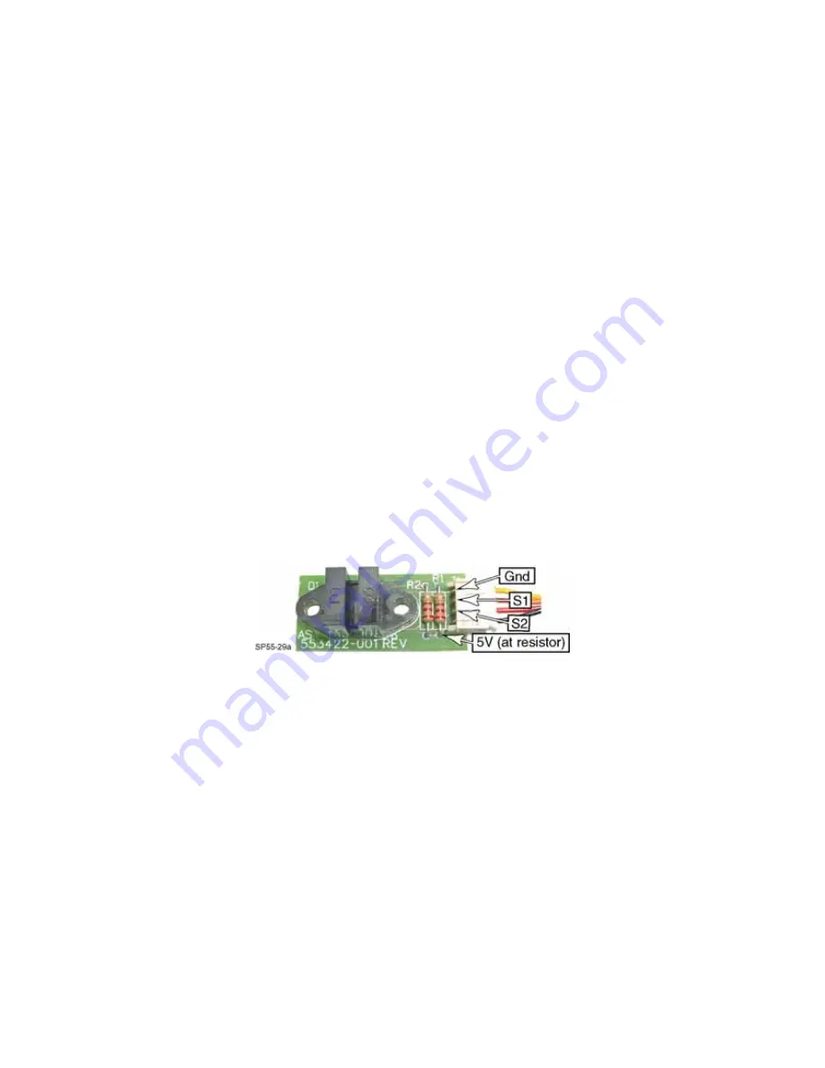
Because the ribbon motion sensor has two channels, the only way to
verify that both channels are functioning is with a voltmeter. Use the test
points in the figure below to test the sensor.
•
To test the laminator index and foil motion sensors (reflective-type) place
an object (such as a card) 1/8 to 1/4 inch in front of the sensor, but not
touching the sensor.
3.
Unplug the printer and swap the sensor with another sensor:
You cannot swap the ribbon motion sensor with any other sensor; it is not
compatible with any other sensor.
•
Because this is a test of the sensor, the original sensor does not need to be
removed. Simply unplug the original sensor from the control board and
plug in a replacement sensor.
•
If a spare sensor is not available, you can use an adjacent sensor from
within the printer. (Except for the ribbon motion sensor, all sensors are
electrically compatible.)
Содержание CP80 Plus
Страница 1: ...Datacard CP80 and CP80 Plus Card Printers Service Manual May 2007 Part No 539490 002 Rev C ...
Страница 14: ...1 4 Introduction ...
Страница 17: ...CP80 and CP80 Plus Service Manual 2 3 Print Engine Functional Block Diagram ...
Страница 18: ...2 4 Theory of Operation Laminator Functional Block Diagram ...
Страница 22: ...2 8 Theory of Operation LCD Service Mode Menu Diagram ...
Страница 52: ...2 38 Theory of Operation ...
Страница 158: ...6 6 Removal and Replacement Print Engine Front Wire Routing Diagram ...
Страница 159: ...CP80 and CP80 Plus Service Manual 6 7 Print Engine Duplex and Printhead Wire Routing Diagram ...
Страница 160: ...6 8 Removal and Replacement Laminator Front Wire Routing Diagram ...
Страница 161: ...CP80 and CP80 Plus Service Manual 6 9 Laminator Rear Wire Routing Diagram ...
Страница 162: ...6 10 Removal and Replacement Power Supply Wire Routing Diagram ...
Страница 163: ...CP80 and CP80 Plus Service Manual 6 11 Print Engine Cable Connection Diagram ...
Страница 164: ...6 12 Removal and Replacement Laminator Cable Connection Diagram ...


