


2-26
Theory of Operation
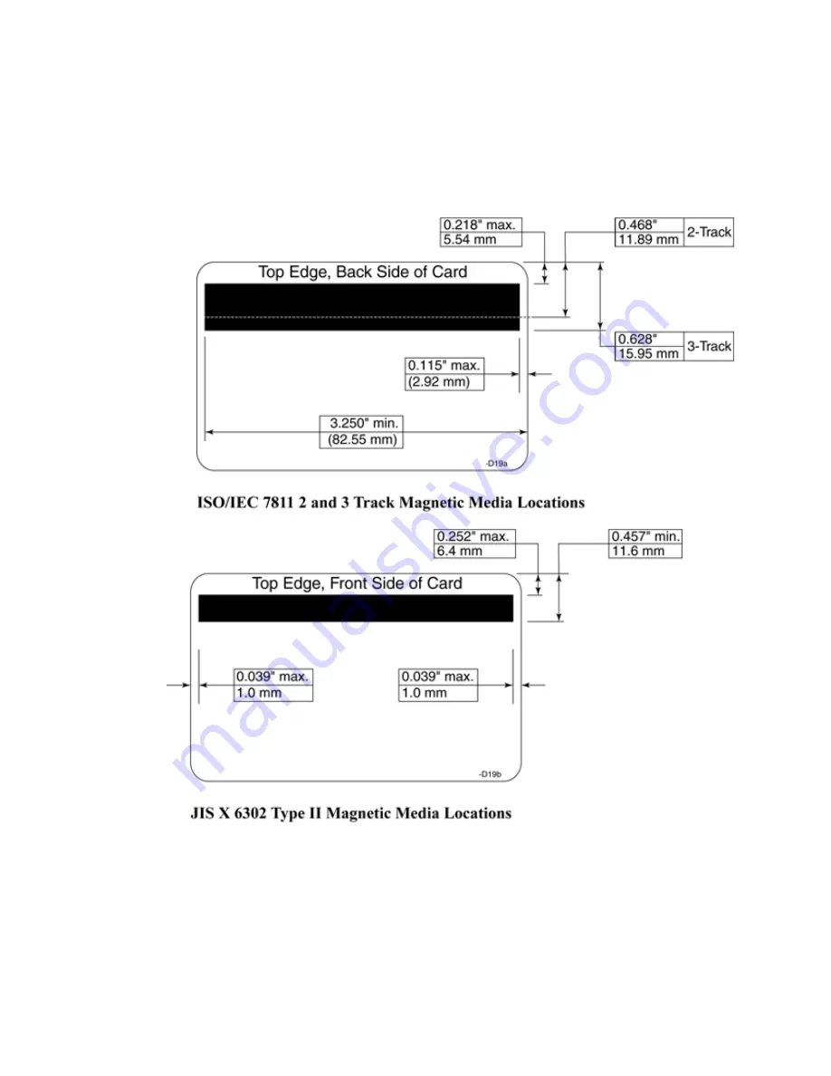
Magnetic Media Locations
The physical location and size of the magnetic stripe on a card follows the
specifications outlined in the two drawings below. The first graphic is for a two
or three track card (ISO/IEC and JIS Type I). (Note that under the ISO and JIS
standards, even if only one of the three tracks is used, the minimum track size
follows this specification.)
Содержание CP80 Plus
Страница 1: ...Datacard CP80 and CP80 Plus Card Printers Service Manual May 2007 Part No 539490 002 Rev C ...
Страница 14: ...1 4 Introduction ...
Страница 17: ...CP80 and CP80 Plus Service Manual 2 3 Print Engine Functional Block Diagram ...
Страница 18: ...2 4 Theory of Operation Laminator Functional Block Diagram ...
Страница 22: ...2 8 Theory of Operation LCD Service Mode Menu Diagram ...
Страница 52: ...2 38 Theory of Operation ...
Страница 158: ...6 6 Removal and Replacement Print Engine Front Wire Routing Diagram ...
Страница 159: ...CP80 and CP80 Plus Service Manual 6 7 Print Engine Duplex and Printhead Wire Routing Diagram ...
Страница 160: ...6 8 Removal and Replacement Laminator Front Wire Routing Diagram ...
Страница 161: ...CP80 and CP80 Plus Service Manual 6 9 Laminator Rear Wire Routing Diagram ...
Страница 162: ...6 10 Removal and Replacement Power Supply Wire Routing Diagram ...
Страница 163: ...CP80 and CP80 Plus Service Manual 6 11 Print Engine Cable Connection Diagram ...
Страница 164: ...6 12 Removal and Replacement Laminator Cable Connection Diagram ...