102 · vacon
Description of parameters
Tel. +358 (0)201 2121 • Fax: +358 (0)201 2121 205
5
5.9.9
Over Load Protection
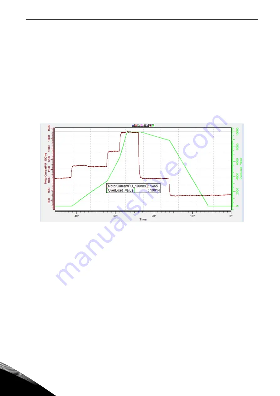
With this function it is possible to select if Current %, Active Current or Reactive Current is used for
over load protection. Over Load is based on internal counter that is increased when input value is
above 105 % level and decreased when below 105 % level. The increase and decrease occurs every
100 ms.
Tripping is made when over load counter value is over 10 000.
With parameters you can define the increase (Over load maximum step) at maximum defined input
level (Over Load Maximum Input). These points define the slope for the function. For example, if the
input value is in the middle of 105 % and Over Load Maximum Input values, the counter is increased
by a half of the Over Load Maximum step.
Figure 40.
2.9.9.1
Response to over load ID1838
“OverLoadResponse”
0 = No response
1 = Warning
2 = Fault
2.9.9.2
Over Load Signal
ID1837
“OverLoadSignal”
0 = Not Used
1 = Total Current [%] (FW: MotorCurrentPU_100ms)
2 = Active Current
3 = Reactive Current
2.9.9.3
Over Load Maximum Input
ID1839
“OverLoadMaxIN”
Input value level where the over load counter is increased with maximum step defined by
P2.9.9.4


