


5 How to Control the Frequency Converter
5.1 PDO Communication
The VLT
®
AutomationDrive uses the following profiles:
•
Frequency converter profiles
•
CANopen DS 402 profile
For each of the two profiles there is a set of SDO objects
that is only accessible if the profile is activated in
8-10 Control Word Profile
. The change will first be active at
the next power up. The PDO communication has to be
configured, where a subset of SDOs can be mapped into
PDOs for cyclic communication.
PDO communication is reserved for high speed cyclic
access to parameters for control and status of the
frequency converter. The PLC sends out process control
data, and the frequency converter responds with a PDO
containing process status data. In the Danfoss POWERLINK
interface both PDOs can be freely be configured.
Select the signals for transmission from the master to the
frequency converter via the PLCs configuration tool.
12-21 Process Data Config Write
,
12-22 Process Data Config
Read
and
12-23 Process Data Config Write Size
will be set
from the PLC and can be used to control if the configu-
ration has been sent correctly from the PLC.
The POWERLINK option has only one PDO available: PDO
23. The PDO 23 is flexible in size and is adjustable to fit all
needs (max. 10 PCDs). The selection is made in the master
configuration and is then automatically downloaded to the
frequency converter during the transition from Init to Pre-
Op. No manual setting of PPO types in the frequency
converter is required.
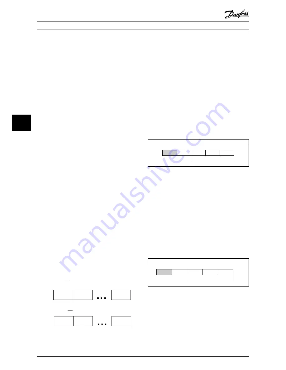
Selection
[1] Standard telegram 1
is equivalent to PDO 23.
Receive PDOs (PLC
Drive)
Transmit PDOs (Drive
PLC)
PCD 9
write
PDO 23
PCD 0
CTW
PCD 1
REF
PCD 9
read
PCD 0
STW
PCD 1
MAV
PDO 23
130BC177.10
Illustration 5.1 Standard Telegram
5.2 Process Data
Use the process data part of the PDO for controlling and
monitoring the frequency converter via the POWERLINK.
5.2.1 Process Control Data
The example in
Table 5.1
shows control and reference sent
from the PLC to the frequency converter, and status word
and main actual value sent from the frequency converter
to the PLC.
Master to slave
0
1
2
......
9
CTW
MRV
PCD
......
PCD
PCD write
Table 5.1 Process Control Data (PCD)
PCD 0 contains a 16-bit control word where each bit
controls a specific function of the frequency converter, see
5.3 Control Profile
. PCD 1 contains a 16-bit speed set point
in percentage format. See
5.2.3 Reference Handling
.
The content of PCD 2 to PCD 9 is read only.
5.2.2 Process Status Data
Process data sent from the frequency converter contain
information about the current state of the frequency
converter.
Slave to master
0
1
2
......
9
STW
MAV
PCD
......
PCD
PCD read
Table 5.2 Process Status Data
PCD 0 contains a 16-bit status word where each bit
contains information regarding a possible state of the
frequency converter.
PCD 1 contains per default the value of the current speed
of the frequency converter in percentage format (see
5.2.3 Reference Handling
).
How to Control the Frequenc...
MCA 123 POWERLINK Operating Instructions
14
MG92C102 - VLT
®
is a registered Danfoss trademark
5
5