


Cascade Controller Option
The instant effect of the fixed speed pump creates
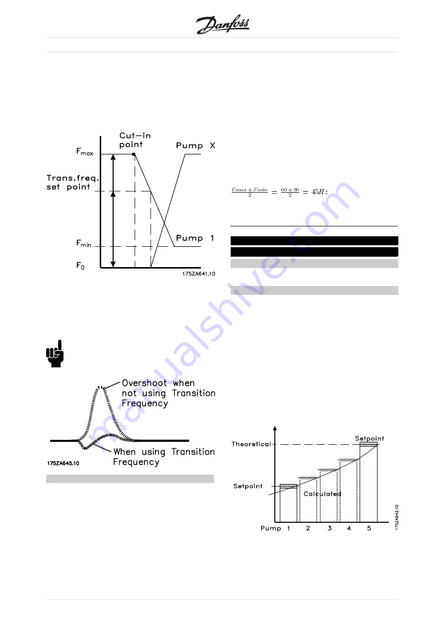
a momentary overpressurization until the adjustable
speed pump decelerates. This is undesirable in
most situations. To avoid this, this drive can be
programmed to decelerate to a transition frequency
before starting the fixed speed pump.
The opposite process occurs during destaging
where a momentary pressure drop is avoided by
increasing the speed of the adjustable speed pump.
Therefore, set a transition frequency roughly half-way
between minimum and maximum frequency.
NB!:
Ensure that the transmission frequency is set
within the minimum frequency and maximum
set in parameters 201 and 202.
Description of choice:
Adjust the transition frequency to the best compromise
to prevent momentary pressure overshoot and a
pressure drop during transition. A very low value for
the transition frequency might cause the check valve
at the discharge of a variable speed pump to close
during the transition, which could add pressure in the
system. Ensure that the transition frequency setting
allows the check valve to remain open.
Example:
Maximum frequency (F
max
) = 60Hz
Minimum frequency (F
min
)= 30Hz
Transistion frequency to be programmed exactly
F
max
and F
min
Then, transition frequency = 45/F
max
= 45/60 =75%
Quick Menu 028 Par. 418 Setpoint 1
(SETPOINT 1)
Value:
Feedback Min. to Feedback Max
✭
0.000
Function:
The default feedback process is used when a
pressure feedback signal is measured at the outlet
of the pumps. The cascade controller uses the
feedback to estimate the setpoint required at
various rates of flow. All other reference signals
are ignored. Setpoint 1 is the minimum pressure
required when the system is running with only the
adjustable frequency drive operating at full speed.
Setpoint 1 is a theoretical value that the cascade
controller uses as an internal reference to calculate
pressure loss in the system under minimum load.
The controller adjusts the internal reference based
upon the number of pumps in operation.
The range is determined by Quick Menu item 14
(parameter 413,
Minimum Feedback
) and Quick Menu
item 015 (parameter 414,
Maximum Feedback
).
When the pressure feedback signal originates at
the far end of the system, the drive does not
need to compensate for system pressure changes
MG.60.I3.02 - VLT is a registered Danfoss trademark
42