


4
First-Time System Setup & Launch
Connecting DVI Video
To connect the DVI video to the VIP-4060 system, follow the steps below:
1.
Insert a male plug into the female jack.
2.
Turn the screws on the male plug clockwise to lock. Refer to
Figure 3
.
Temperature and CAN Light Sensors
To enable temperature and light sensors, follow the steps below while referring
to
Figure 4
:
1.
Connect the Daktronics-supplied sensor cable to the Light/Temp port.
2.
Rotate the connector clockwise a quarter turn to lock.
Phoenix Connection
Use the Phoenix connection to enable peripheral devices such as direct light
sensors. Refer to
Figure 5
.
Network
To connect the VIP-4060 to the network, follow the steps below:
1.
Connect an RJ45 network cable to the network port on the VIP-4060.
Refer to
Figure 6
.
2.
Connect the other end of the cable to the computer or network.
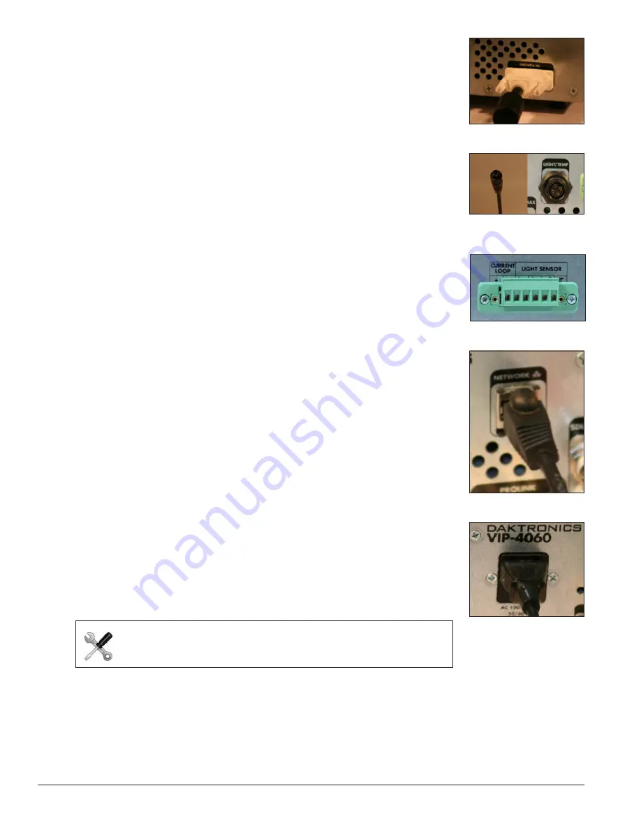
Power
To connect power to the VIP-4060, follow the steps below:
1.
Connect the cord into the jack on the VIP-4060. Refer to
Figure 7
.
2.
Plug the cord into an outlet.
2.2 Computer-to-VIP-4060 Communication
Once the physical connections have been made, navigate to the network address
of the VIP-4060 to run the configuration application stored within the device. The
IP address is located in the documentation that arrived with the equipment or on
the label on the back of the VIP-4060.
Tech Note:
New customers receive the VIP-4060 with a
factory-determined IP address in the equipment documentation. The
DisplayFind utility helps technicians in troubleshooting situations.
Figure 3:
DVI Input
Figure 4:
Sensor Cable
and Port
Figure 5:
Phoenix Connection
Figure 6:
Network Input
Figure 7:
Power Port


