Operation
www.DaikinApplied.com 57
IOM 1281-2 • CENTRIFUGAL WATER CHILLERS
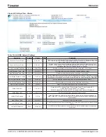
Clearing an Alarm
There are two different indicators that the chiller will generate
when conditions arise that are affecting the chiller operations.
Warnings are indicated in yellow text on the HMI and
communicate that the chiller should be serviced but allow the
chiller to keep running. Warnings cannot be cleared manually
and will be cleared automatically when the issues has been
resolved.
Critical Alarms will always shutoff the chiller. Critical Alarms that
do not require external intervention may attempt to auto-clear
once conditions return to normal (Pressure and Temperature
Alarms). Auto-cleared Critical Alarms will become yellow and
will be displayed as warnings unless there has been 3 within
the hour. After 3 alarms occur within the hour, the Critical
Alarm will be displayed as a Critical Alarm by being indicated
in Red on the HMI and will prevent the chiller from running until
manually cleared at the HMI or via the BAS. Critical Alarms
that require external intervention (Communication and Sensor
Alarms) will immediately show up as Red Alarms on the HMI
and prevent the chiller from running until manually cleared at
the HMI or via the BAS, after the condition has been resolved.
Repeated manual clearing of Critical Alarms via the HMI or the
BAS without resolving the cause of the Alarm may damage the
chiller and void the chiller warranty.
Although the Alarm History Screen only displays the most
current alarms, a record of ALL alarms is stored in the Unit
Control Processor. Note that this record may include alarms
that occurred when the chiller was not yet fully assembled in
the factory. This record is maintained even if the Unit Control
Processor is powered off. When the HMI is powered back on,
the last 18 alarms for the current date will show on the Alarm
History Screen and all alarm history will still be available for
download.
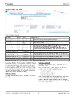
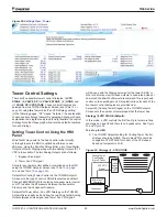
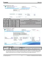
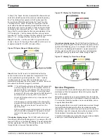
Figure 68: Active Alarm View Screen
Содержание WDC
Страница 4: ......
Страница 21: ...Installation www DaikinApplied com 21 IOM 1281 2 CENTRIFUGAL WATER CHILLERS Figure 16 Field Wiring Schematic...
Страница 22: ...IOM 1281 2 CENTRIFUGAL WATER CHILLERS 22 www DaikinApplied com Installation Figure 17 Compressor Control Box...
Страница 23: ...Installation www DaikinApplied com 23 IOM 1281 2 CENTRIFUGAL WATER CHILLERS Figure 18 Unit Control Box...
Страница 38: ...IOM 1281 2 CENTRIFUGAL WATER CHILLERS 38 www DaikinApplied com Operation Figure 39 Unit Detail View Screen...
Страница 72: ......

