Operation
www.DaikinApplied.com 33
IOM 1281-2 • CENTRIFUGAL WATER CHILLERS
Operation
WARNING
Electric shock hazard. Can cause personal injury or equipment
damage. This equipment must be properly grounded.
Connections to and service of the MicroTech control panel
must be performed only by personnel that are knowledgeable
in the operation of the equipment being controlled.
CAUTION
Static sensitive components. A static discharge while handling
electronic circuit boards can damage components. Discharge
any static electrical charge by touching the bare metal inside
the control panel before performing any service work. Never
unplug any cables, circuit board terminal blocks, or power
plugs while power is applied to the panel.
CAUTION
Do not install any non-Daikin Applied authorized software or
alter operating systems in any unit microprocessor, including
the interface panel. Failure to do so can cause malfunction of
the control system and possible equipment damage.
Dual/Multi-Chiller Operation
Multiple Chiller Setup
Single compressor chillers WSC and dual compressor chillers
WDC and WCC have their main control components factory
wired to an internal pLAN network so that the components
can communicate with each other, within the chiller itself. On
multi-chiller applications, up to four chillers, either single, or
dual compressor, can be interconnected by this internal pLAN.
All that is required is simple field RS485 interconnecting wiring,
the addition of accessory communication isolation board(s)
485OPDR (Daikin Applied P/N 330276202), and MicroTech
II control settings. The isolation board can be purchased with
the unit or separately, during or after chiller installation. The
number of boards required equals the number of chillers minus
one.
NOTE:
pLAN multiple chiller interconnection is designed
for parallel chiller installations with the leaving water
sensors in their normal location in the outlet nozzle.
For two units in series operation, the leaving chilled water
sensors must be moved far enough downstream from the last
chiller to insure reading a thoroughly mixed water temperature.
Passing through one or two elbows will usually suffice. Series
chillers are normally single pass resulting in undesirable
temperature stratification at the outlet nozzle.
Connectability
Centrifugal models WSC and WDC of various vintages with
MicroTech controllers can be interconnected, but all must be
loaded with the most recent control software.
Responsibilities
Unless otherwise stated in the contract documents, the
interconnecting MicroTech pLAN RS485 multiple chiller wiring
between chillers is the responsibility of the installing contractor
and should be completed prior to start-up. The Daikin Applied
service technician is responsible for checking the wiring and
making the appropriate control changes.
pLAN Wiring
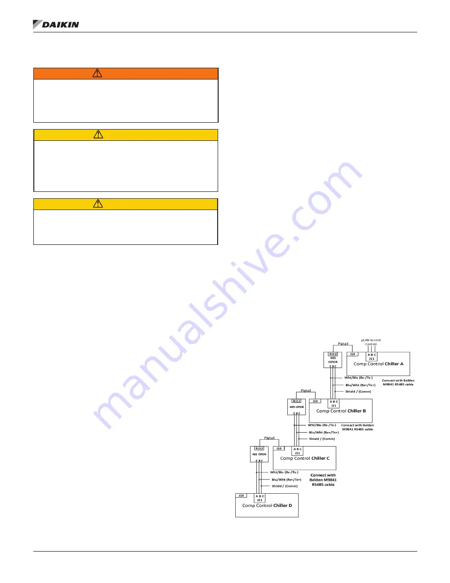
The first chiller in the connection can be designated as Chiller
A. The isolation board is attached to the DIN rail adjacent to
the Chiller A compressor controller. The isolation board kit has
a pigtail that plugs into J10 on the compressor controller.
Two Chillers:
If only two chillers are to be connected Belden
M9841 (RS 485 Spec Cable) is wired from the isolation
board (terminals E, B, & C) on Chiller A to the J11 port on the
compressor controller of Chiller B. At J11, The shield from C
connects to the GND, the blue/white wire from B connects to
the center (+) connection, and the white/blue from E to the
(-) connection. Note that Chiller B does not have an isolation
board. The last chiller (B in this case) to be connected does not
need an isolation board.
Three or Four Chillers:
If three or four chillers are to be
connected, the interconnecting wiring is still made to B’s
J11 port. Now the second chiller (Chiller B) must have an
isolation board that will be plugged into Chiller B’s pLAN J10
port on the compressor controller. Note: Chiller B will look like
chiller A. The wiring from Chiller B will be the same with the
Belden cable as from Chiller A to B, connecting to Chiller C
Compressor controller J11 port. The last Chiller in the network
will not have an isolation board.
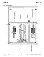
Figure 32: pLAN Communication Wiring
Содержание WDC
Страница 4: ......
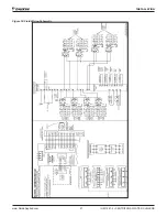
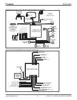
Страница 21: ...Installation www DaikinApplied com 21 IOM 1281 2 CENTRIFUGAL WATER CHILLERS Figure 16 Field Wiring Schematic...
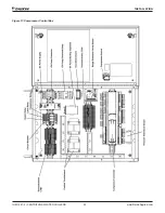
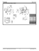
Страница 22: ...IOM 1281 2 CENTRIFUGAL WATER CHILLERS 22 www DaikinApplied com Installation Figure 17 Compressor Control Box...
Страница 23: ...Installation www DaikinApplied com 23 IOM 1281 2 CENTRIFUGAL WATER CHILLERS Figure 18 Unit Control Box...
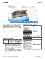
Страница 38: ...IOM 1281 2 CENTRIFUGAL WATER CHILLERS 38 www DaikinApplied com Operation Figure 39 Unit Detail View Screen...
Страница 72: ......

