

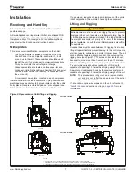
Installation
www.DaikinApplied.com 13
IOM 1281-2 • CENTRIFUGAL WATER CHILLERS
Relief Valves
As a safety precaution and to meet code requirements, each
chiller is equipped with pressure relief valves located on
the condenser and evaporator for the purpose of relieving
excessive refrigerant pressure (caused by equipment
malfunction, fire, etc.) to the atmosphere.
Table 3: WDC, WCC A Vintage Relief Valve Data
Evaporator
Condenser
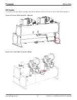
Oil Sump
Location
Top
Top
Top
Setting (psi)
200
225
200
Discharge Capacity
(lb/min air)
75.5
84.4
5
Qty
2 for 16’ shells
2 for 20’ shells
4 for 16’
shells
4 for 20’
shells
1 for
079-126
models
Connection Size
1.0-inch NPT
3/8-inch
NPT
Most codes require that relief valves be vented to the outside
of a building. Relief piping connections to the relief valves must
have flexible connectors.
CAUTION
Units are shipped with refrigerant valves closed to isolate the
refrigerant in the unit condenser. Valves must remain closed
until startup by the factory service technician.
Remove plastic shipping plugs (if installed) from the inside of
the valves prior to making pipe connections. Whenever vent
piping is installed, the lines must be in accordance with local
code requirements; where local codes do not apply, the latest
issue of ANSI/ASHRAE Standard 15 code recommendations
must be followed.
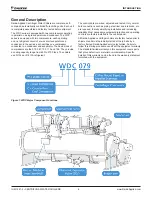
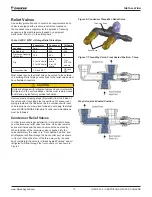
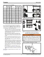
Condenser Relief Valves
In order to ensure proper installation, it is important to know
how the three-way relief valve functions. One valve remains
active at all times and the second valve acts as a standby.
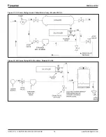
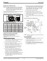
When the stem of the three-way valve is pushed into the
valve completely, the valve is in “Front Seated Position” and
all refrigerant will flow through the back outlet port, as shown
in
Figure 6
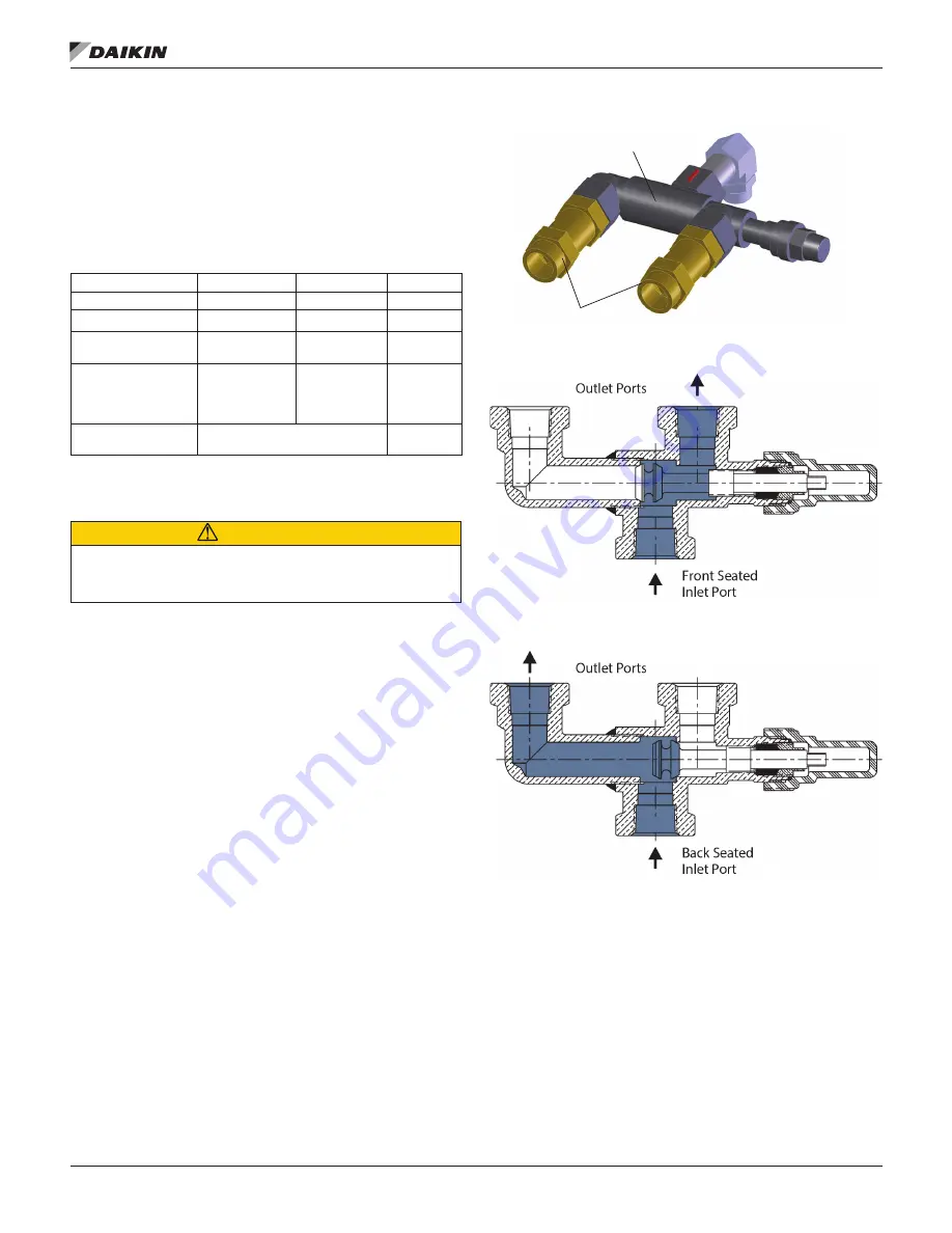
. When the stem of the three-way valve is pulled
back completely, the valve is in “Back Seated Position” and all
refrigerant will flow through the front outlet port, as shown in
Figure 7
.
Figure 6: Condenser Three-Way Relief Valve
Figure 7: Three-Way Valve, Front Seated Position Three
Way Valve, Back Seated Position
Three-Way Valve
Relief Valves
Содержание WDC
Страница 4: ......
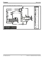
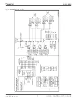
Страница 21: ...Installation www DaikinApplied com 21 IOM 1281 2 CENTRIFUGAL WATER CHILLERS Figure 16 Field Wiring Schematic...
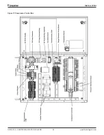
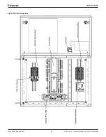
Страница 22: ...IOM 1281 2 CENTRIFUGAL WATER CHILLERS 22 www DaikinApplied com Installation Figure 17 Compressor Control Box...
Страница 23: ...Installation www DaikinApplied com 23 IOM 1281 2 CENTRIFUGAL WATER CHILLERS Figure 18 Unit Control Box...
Страница 38: ...IOM 1281 2 CENTRIFUGAL WATER CHILLERS 38 www DaikinApplied com Operation Figure 39 Unit Detail View Screen...
Страница 72: ......