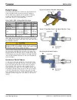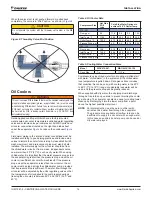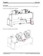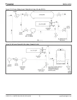
Installation
www.DaikinApplied.com 27
IOM 1281-2 • CENTRIFUGAL WATER CHILLERS
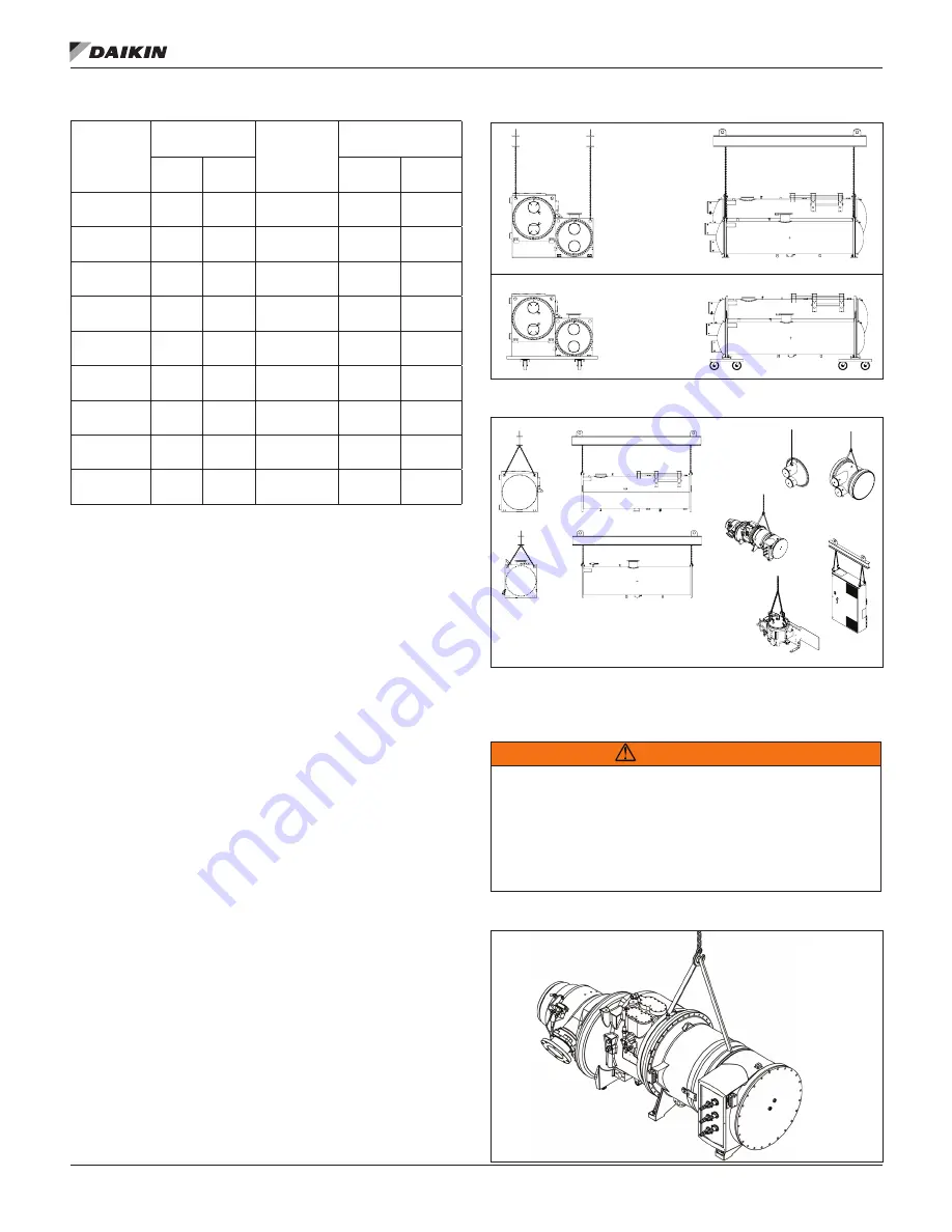
Table 7: Vessel Component Weights
* Component weights based on largest unit with standard tube configuration.
Knockdown Rigging/Lifting Guidelines
To properly rig or lift separated assemblies and components,
consult a licensed, certified rigging specialist.
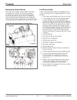
• Lifting holes located in the tubesheets should be used to
attach chain hoists for moving connected vessel stacks
or individual evaporator/condenser assemblies. Rolling
dollies supporting the full vessel width may also be used
under the tubesheets on each end.
• Lift the VFD / Starter by attaching chain hoists to the
lifting brackets located at the top corners of the cabinet.
Rolling dollies supporting the full cabinet width may also
be used.
• Lift the oil pump assembly by attaching eye bolts in the
2 holes on the top of the oil pump and then connect the
chain hoists. Eye bolts are not provided. Rolling dollies
may also be used.
• Lift dished waterbox head assemblies by attaching chain
hoists to the lifting lugs on the head. The location of the
lifting lug will vary depending on size of the waterbox and
nozzle configuration. Rolling dollies may also be used.
• Lift marine waterbox head assemplies by wrapping lifting
straps around the body of the waterbox. Rolling dollies
may also be used.
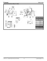
• Lift the compresser by wrapping lifting straps around
the body of the assembly, see
Figure 23.
Rolling dollies
supporting the full length of the compressor may also be
used.
Note component weights and dimensions are listed in
Table 7
and Table 8.
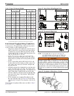
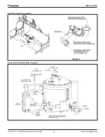
Figure 21: Vessel Stack Lifting/Rigging Setup
Figure 22: Component Lifting Setup
NOTE:
The spreader bar in
Figure 21
and
Figure 22
are representations only and may not reflect the
appearance of the actual spreader bar needed.
WARNING
Improper rigging, lifting, or moving of a unit can result in
property damage, severe personal injury or death. Follow
rigging and moving instructions carefully. Daikin Applied is not
a licensed nor certified rigging specialist. It is the customer’s
responsibility to consult a certified rigging contractor to rig,
lift, and move components and subcomponents properly and
safely.
Figure 23: Compressor Lifting Setup - Closeup
Evaporator
Dry Weight
Condenser
Dry Weight
lbs
kg
lbs
kg
3016-WDC
5235
2374
3016-WDC
5869
2662
3616-WDC
6928
3142
3616-WDC
8197
3718
4216-WDC
12025
5454
4216-WDC
14489
6572
4816-WDC
16800
7620
4816-WDC
19412
8805
4220-WDC
14988
6798
4220-WDC
18284
8293
4820-WDC
20523
9309
4820-WDC
23724
10761
3620-WCC
8756
3971
3620-WCC
11893
5394
4220-WCC
12674
5748
4220-WCC
16856
7645
4820-WCC
18495
8389
4820-WCC
21993
9975
BACK VIEW
END VIEW
BACK VIEW
END VIEW
VESSEL STACK - LIFTING
VESSEL STACK - RIGGING
CONDENSER ASSEMBLY
BACK VIEW
TUBE PATTERN
NOT SHOWN
CONDENSER ASSEMBLY
END VIEW
EVAPORATOR ASSEMBLY
BACK VIEW
TUBE PATTERN
NOT SHOWN
EVAPORATOR ASSEMBLY
END VIEW
HEAD ASSEMBLY
ISO VIEW
WATERBOX ASSEMBLY
ISO VIEW
COMPRESSOR ASSEMBLY
ISO VIEW
VFD / STARTER
ISO VIEW
OIL PUMP ASSEMBLY
ISO VIEW
FIELD - FULL KNOCKDOWN
LIFTING
Содержание WDC
Страница 4: ......
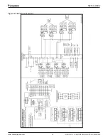
Страница 21: ...Installation www DaikinApplied com 21 IOM 1281 2 CENTRIFUGAL WATER CHILLERS Figure 16 Field Wiring Schematic...
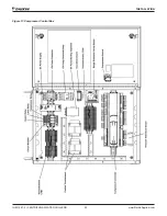
Страница 22: ...IOM 1281 2 CENTRIFUGAL WATER CHILLERS 22 www DaikinApplied com Installation Figure 17 Compressor Control Box...
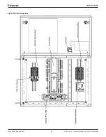
Страница 23: ...Installation www DaikinApplied com 23 IOM 1281 2 CENTRIFUGAL WATER CHILLERS Figure 18 Unit Control Box...
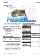
Страница 38: ...IOM 1281 2 CENTRIFUGAL WATER CHILLERS 38 www DaikinApplied com Operation Figure 39 Unit Detail View Screen...
Страница 72: ......

