Installation
www.DaikinApplied.com 29
IOM 1281-2 • CENTRIFUGAL WATER CHILLERS
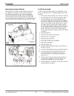
Separating Vessel Stacks
After removing compressor and associated lines for Type
A knockdown, the liquid line connecting the evaporator
and condenser as well as the oil sump would need to be
removed to separate the vessels.
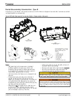
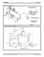
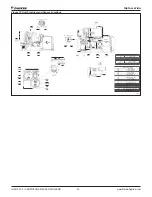
Figure 27
illustrates the
mechanical break points for the liquid line where blockoffs
must be provided on each vessel.
Figure 28
shows the various
connections for oil sump assemblies that need block off caps.
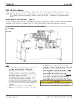
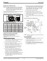
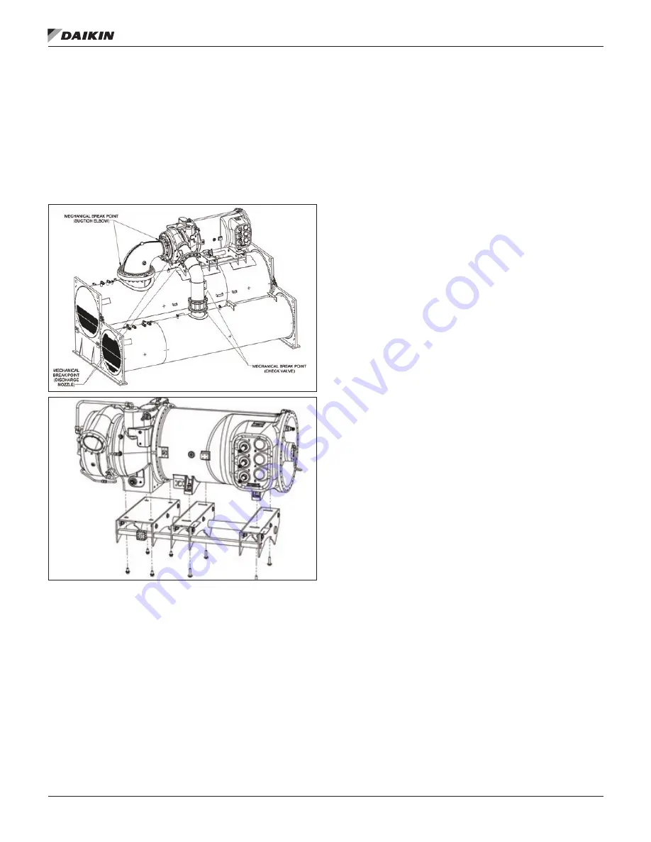
Figure 26: Compressor Removal / Re-Attachment
Unit Reassembly
The level of disassembly required for unit installation will be
varied. For all steps, use new refrigerant gaskets and o-rings
provided.
1.
If the vessels were separated, rejoin them as a first step.
2. The compressor and its suction and discharge piping
should be installed on the vessel stack before any
other lines are attached. Mounting bolts and additional
hardware are shipped as a kit. Leave the mounting bolts
loose until the suction and discharge lines are in place
and aligned. Before tightening the couplings, position
the suction and discharge piping so that the compressor
can be aligned properly. When piping is in the correct
position, secure the compressor mounting bolts and
proceed with installing the couplings using a thin coating
of lubricant.
3. Install the liquid line
4. Install the oil sump and oil cooler lines
5. Install the motor cooling lines
6. Intall the liquid injection line
7. Install hot gas bypass line if applicable
8. Install motor drain lines
9. Install oil eductor line
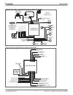
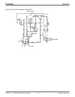
10. Install the electrical wiring and sensor connections as
shown in
Figure 29
.
11. Re-attach all associated power wiring & Ethernet cable.
12. Pull vacuum at evaporator and compressor to 300
microns and perform a standing hold to verify no
moisture or leaks - do not allow rise of 300 microns
within 1 hour.
13. Charge unit with required amounts of refrigerant and
oil and perform refrigerant leak check to ensure all
connections and fittings are securely fastened.
14. Insulate evaporator, compressor, suction line, and other
required areas as necessary.
Содержание WDC
Страница 4: ......
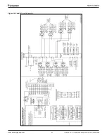
Страница 21: ...Installation www DaikinApplied com 21 IOM 1281 2 CENTRIFUGAL WATER CHILLERS Figure 16 Field Wiring Schematic...
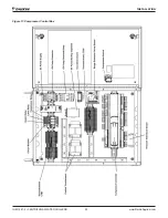
Страница 22: ...IOM 1281 2 CENTRIFUGAL WATER CHILLERS 22 www DaikinApplied com Installation Figure 17 Compressor Control Box...
Страница 23: ...Installation www DaikinApplied com 23 IOM 1281 2 CENTRIFUGAL WATER CHILLERS Figure 18 Unit Control Box...
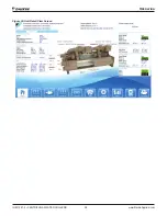
Страница 38: ...IOM 1281 2 CENTRIFUGAL WATER CHILLERS 38 www DaikinApplied com Operation Figure 39 Unit Detail View Screen...
Страница 72: ......

