Cleaning and Flushing System
1.
Prior to first operation of any conditioner, the water
circulating system must be cleaned and flushed of all
construction dirt and debris. If the conditioners are
equipped with water shutoff valves, either electric
or pressure operated, the supply and return runouts
must be connected together at each conditioner
location. This will prevent the introduction of dirt into
the unit. Additionally, pressure operated valves only
open when the compressor is operating.
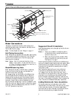
Figure 6: Temporary Connection for Flushing System Piping
Swivel
Adapter 1/2" MPT
x 37 Flare JIC
Supply
Valve
Return Valve
Floor Line
1/2" (13mm) MPT
Steel Fitting
1/2" (13mm)
I.D. Hose
2.
The system should be filled at the city water makeup
connection with all air vents open. After filling, vents
should be closed. The contractor should start main
circulator with pressure reducing valve makeup
open. Vents should be checked in sequence to bleed
off any trapped air to assure circulation through all
components of the system. Power to the heat rejector
unit should be off, and the supplementary heat
control set at 80˚F (27˚C). While circulating water,
the contractor should check and repair any leaks in
the piping. Drains at the lowest point(s) in the system
should be opened for initial flush and blowdown,
making sure city water fill valves are set to make up
water at the same rate. Check the pressure gauge
at pump suction, and manually adjust the makeup to
hold the same positive steady pressure, both before
and after opening the drain valves. Flush should
continue for at least two hours, or longer if required,
to see clear, clean drain water.
3.
Supplemental heater and circulator pump should be
shut off. All drains and vents should be opened to
completely drain down the system. Short circuited
supply and return runouts should now be connected
to the conditioner supply and return connections.
Teflon tape is recommended versus pipe dope for
pipe thread connections. Use no sealers at the
swivel flare connections of hoses.
4.
Trisodium phosphate was formerly recommended as a
cleaning agent during flushing. However, many states
and localities ban the introduction of phosphates into
their sewage systems. The current recommendation is
to simply flush longer with 80˚F (27˚C) water.
5.
Refill the system with clean water. Test and treat as
required to leave the water slightly alkaline (pH 7.5
to 8.5). The specified percentage of antifreeze may
also be added at this time. Use commercial grade
antifreeze designed for HVAC systems only. Do not
use automotive grade antifreeze.
6.
Set the system control and alarm panel heat add
setpoint to 70˚F (21˚C) and heat rejection setpoint
to 85˚F (29˚C). Supply power to all motors and
start the circulating pumps. After full flow has been
established through all components, including the
heat rejector (regardless of season), and air vented
and loop temperatures stabilized, each of the
conditioners will be ready for check, test, and start-
up and for air and water balancing.
7.
It is not Daikin’s policy to make recommendations
on water treatment. The general contractor or owner
should contact a local water treatment company
regarding water treatment. However, this topic is
critical and care should be taken to make sure it
is done properly to prevent problems related to
flow. A fouled closed loop water system will lead to
premature component failure.
Standard Electrical Connection
Each chassis comes with a junction box mounted on
the side of the chassis and contains the field electrical
connection.
Note:
If electrical wiring or conduit comes through the
floor, all wires or conduit should be sealed at this
point. It will prevent any condensation or water
leakage that may occur due to lack of preventive
maintenance. Each unit has an internal conden
-
sate trap that will require cleaning. We suggest
wiring coming through the wall should also be
sealed to stop cold air infiltration through the wall
cavity which could affect unit thermostat operation.
Remove the junction box cover, selecting the proper
knockout and remove it. Install a strain relief and pass the
wires through the strain relief into the junction box making
the connection and reinstall the junction box cover.
Note:
Check the local code concerning correct electrical
connection.
Cord & Plug Electrical Connection (Field
Installed)
Cord connected equipment comes with a box and
appropriate voltage receptacle. However, a disconnect
switch and fuses can also be provided in the box. As an
option, the box comes factory mounted on the backwrap
and is ready to be field wired to the incoming power. The
box is mounted on the same side as the piping.
It is the responsibility of the installing contractor to make
the proper electrical connection to the electrical box, using
the same method as described in the standard electrical
connection. See Figure 7 and Figure 8 on page
12
.
www.DaikinApplied.com 11
IM 447-11
Содержание WAA
Страница 2: ......
Страница 35: ...Notes Comments Form WS CTS 00 01 Rev 4 14 www DaikinApplied com 35 IM 447 11...

