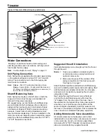
Figure 2: Chassis (Left-hand slope top unit shown)
9.0"
(229mm)
Control Diagram
Compressor/Control Box
Access Cover
Escutcheon Plate
Wiring Diagram
Fan/Coil Section Access Panel
Condensate Line–14" (356mm) Clear Vinyl
Hose Clamp
Air Coil
Water Return
W
ater Supply
Junction Box
Flexible Hoses
Ball Valves
Electric Conduit
5.0"
(127mm)
All Pipe Fittings Are To Be
Field Installed
Water Connections
All piping connections should be made using good
plumbing practices and in accordance with any and all
local codes that may apply.
Note:
It will be helpful to read, “Piping” on page
10
Unit Piping Connection
Each heat pump is supplied with extended copper tubing
on the water-to-refrigerant coil and 1/2" (12.7mm) OD
tubing. The connections are for both the supply and
return water connections.
Note: Valves – Shut off Combination Balancing Valves,
Hoses
– Supply Return, Condensate Drain Hose and
90
º
Elbows are all factory available as accessories, (to
be mounted in the field by others).
Shutoff/Balancing Valve
Each heat pump requires a shutoff valve on both the
supply and return lines for easy serviceability and
removal if it becomes necessary.
We suggest using our combination shutoff/balancing
valves installed in the field between the contractor’s
piping and the heat pump unit. Constructed of brass
and rated at 400 psig (2758 kPa) maximum working
pressure. Valves have a built-in adjustable memory
stop to eliminate rebalancing. The valve installed on the
return line acts as a balancing valve to adjust the proper
water flow. Each shutoff/balancing valve has 1/2" FPT ×
1/2" FPT threaded connections.
Suggested Hose Kit Installation
Field installed piping can be brought up from the floor or
through the wall.
Notes:
1. Hoses are available in multiple lengths to
acommodate various piping locations and
optional components.
2
.
Make sure the pipes fit the confines of the
piping compartment of the heat pump unit.
See Figure 4 on page
9.
Attach the field installed combination shut/off balancing
valve to the building water supply and return piping. Next
add the female pipe adapter connection to unit supply
and return coil connection by sweating them in place
using silver solder.
Next, using the specified hose kit, screw the fixed
end into the shut-off/balancing valve. Remove the
1/2" adapter from the other end of the hose. Insert
the adapter into the female fitting. Using two crescent
wrenches, one to hold the pipe connection and the
second to tighten the adapter, insert the swivel end of
the hose on the adapter and tighten. This completes the
hose connection to standard heat pump equipment.
Adding Motorized & Valve Assemblies
All console water source heat pumps can be field
installed with a motorized valve. All valves are mounted
on the return line of each unit. All valve assemblies
terminate with 1/2" NPT threaded connections and will
also accommodate factory supplied hose kits.
IM 447-11
8
www.DaikinApplied.com
Содержание WAA
Страница 2: ......
Страница 35: ...Notes Comments Form WS CTS 00 01 Rev 4 14 www DaikinApplied com 35 IM 447 11...

