background image

Unit Operation – General

Mark IV/AC-Control Units 

Note: 

At start-up of unit, ensure that temperature, flow rate 

and voltage are within specified limits required for 

proper unit operation. Each unit has its own control 

or remote control, utilizing an internal thermostat (unit 

mounted) and touch-pad selector switch or a wall 

mounted thermostat (remote control units). 

Each unit has a Mark IV/AC version printed circuit board. 

Its control is available in unit mounted or remote wall 

thermostat. The Mark IV/AC controller has a 14-pin low 

voltage terminal strip for a hardwired interface for all 

the necessary field connections interfacing to external 

equipment (see Table 8). The low voltage output from 

the low voltage terminal strip is always 24 volts AC. 

Terminals F and V on the low voltage terminal strip 

supply 24 volts DC-power.

Table 8: 14-Position Terminal Strip

Pin

Designation

Description

Transformer ground (0vac)

R

 Transformer supply (24vac)

– DC power connection

Pump request output

A

Alarm fault output

U

Unoccupied input

L

Load shed input

Remote shutdown input

+DC power connection

10 

Y1 

Occupied cooling mode input

11 

W1 

Occupied heating mode input

12 

Fan only input

13 

W2 

Unoccupied heating mode input

14 

Tenant override input

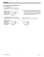
The 24 volt low voltage terminal strip is set up so R-G 

or F-G energizes the fan, R-Y1 or F-Y1 energizes 

the compressor for cooling operation, R-W1 or F-W1 

energizes the compressor and reversing valve for 

heating operation. The reversing valve is energized in 

the heating mode. The circuit board has a fan interlock 

circuit to energize the fan whenever the compressor’s on 

if the thermostat logic fails to do so. 

Remember the output to the wall stat can be AC current 

or DC current. Terminal (R) on the wall stat can be 

connected to terminal (R) on the PC board for AC voltage 

or to terminal (F) on the PC board for DC voltage.
AC current 

DC current

R to G = fan only  

F to G = fan only

R to Y1 = cooling 

F to Y1 = cooling

R to W1 = heat  F to W1 = heat

Continuous Fan:

 Units are factory wired for continuous 

operation. When power is applied and the start switch is 

depressed, the fan will run. 

Cooling or Heating – Auto Operation:

 Rotate the 

thermostat knob to either warmer or cooler. Select fan 

speed. Depress the start button. Unit will start within 0 to 

32 seconds. 

Lockout Circuit:

 Each unit has its own lockout circuit 

to lock out compressor operation when an abnormal 

condition should appear. During unit operation, the 

compressor will be automatically turned off due to one 

of the two safety openings. High pressure is set at 600 

psi (4136 kPa) and low temperature switch is set at 28˚F 

(-2˚C). Condensate overflow and brownout protection 

are also included. 

Remote Reset of Automatic Lockouts:

 The Remote 

Reset feature provides the means to remotely reset 

automatic lockouts generated by high-pressure and/or 

low-temperature (in heating) faults. When the Mark IV 

board is in automatic lockout due to one of these faults, 

and the cause of the fault condition has been alleviated, 

energizing the O-terminal for 10 seconds or more will 

force the Mark IV board to clear the lockout. A unit power 

cycle can also be used to clear an automatic lockout if 

the conditions causing the fault have been alleviated. 

Fault Retry To Minimize Nuisance Trips:

 The Fault 

Retry feature helps to minimize nuisance trips of 

automatic lockouts caused by high-pressure and/or low-

temperature (in heating) faults. This feature clears faults 

the first two times they occur within a 24-hour period and 

triggers an automatic lockout on the 3rd fault. The retry 

count is reset to zero every 24 hours. 

Cooling or Heating – Manual Operation:

 Rotate the 

thermostat knob to either warmer or cooler. Select fan 

speed, depress the heat or cool button, and unit will start 

within 0 to 32 seconds. 
The Mark IV/AC-circuit board system has built-in 

features such as random start, compressor time delay, 

night setback, load shed, shutdown, condensate 

overflow protection, defrost cycle, brownout, and LED/

fault outputs. Table 9 shows the LED and fault output 

sequences. The 24 volt low voltage terminal strip is set 

so R-G energizes the fan. R-W1 energizes the fan and 

compressor and reversing valve for heating operation.
The reversing valve is set up to be energized in the 

heating mode. The circuit board has a fan interlock circuit 

to energize the fan whenever the compressor is on.

www.DaikinApplied.com 15 

IM 447-11

Содержание WAA

Страница 1: ...els For Replacement of McQuay Console Models WAA WAF WAG WAH WAS WAX WCB WCQ WDA WDB WDC WDD WDE WDF WDG WDH WDJ WDL WDN WDS WDU WDX WDY WDZ WFQ WLA WLB WLC WLL WLZ WMA WMB WMC WMD WME WMF WMG WMH WMJ...

Страница 2: ......

Страница 3: ...lation 19 Multiple Unit Control Panel for Mark IV 20 Field Installed Outside Air Damper Accessory 21 Manual Outside Air Damper 21 Motorized Outside Air Damper 21 Motorized Outside Air Damper Wiring 22...

Страница 4: ...al Capacity 04 6 8 009 9 000 Btuh Nominal Cooling 012 12 000 Btuh Nominal Cooling 015 15 000 Btuh Nominal Cooling 019 19 000 Btuh Nominal Cooling Voltage 05 9 A 115 60 1 Size 009 and 012 only E 208 23...

Страница 5: ...WMO WMR WMS WMY WMZ WZS WZY 1 Field supplied control board 2 Subbase not included Physical Data Table 1 Physical Data Unit Size 009 012 015 019 Fan Wheel D x W in 5 3 4 x 9 15 5 3 4 x 9 15 6 x 7 8 6...

Страница 6: ...overed upon unpacking make a written request for inspection by the carrier s agent within fifteen 15 days of the delivery date and file a claim with the carrier Pre Installation WARNING The installer...

Страница 7: ...se STOP If an outside air damper kit is to be installed refer to Field Installed Outside Air Damper Acces sory on page 21 for the manual damper or the motorized damper kit and install it now 4 Positio...

Страница 8: ...ve a built in adjustable memory stop to eliminate rebalancing The valve installed on the return line acts as a balancing valve to adjust the proper water flow Each shutoff balancing valve has 1 2 FPT...

Страница 9: ...T 50 43 81 1 08 Condensate Hose Connection Each unit is supplied with a 3 4 19mm I D clear vinyl condensate hose internally trapped within the chassis The hose extends 14 356mm out of the chassis with...

Страница 10: ...itate removal for service Hard piping can also be brought directly to the unit although it is not recommended since additional noise 4 Some flexible hose threaded fittings are supplied with sealant co...

Страница 11: ...ater slightly alkaline pH 7 5 to 8 5 The specified percentage of antifreeze may also be added at this time Use commercial grade antifreeze designed for HVAC systems only Do not use automotive grade an...

Страница 12: ...Junction Box Figure 8 Cord plug connection field installed Power Cord Receptacle Plug Fuse Holder Switch Backwrap Fuse Disconnect Box 10 0 254mm 5 00 127mm Figure 9 Cabinet power connection field inst...

Страница 13: ...nimum the other two conditions may not exceed the normal condition for standard units Extended range unit may combine any two maximum conditions but not more than two with all other conditions being n...

Страница 14: ...A Min Volts Min Circuit Ampacity Max Fuse Size Volt Hz Phase kW Amps RLA LRA Nominal Actual 009 208 60 1 1 0 0 62 3 0 3 7 22 0 40 4 10 197 5 0 15 230 60 1 0 75 3 3 3 7 22 0 40 4 10 197 5 0 15 265 60 1...

Страница 15: ...itch is depressed the fan will run Cooling or Heating Auto Operation Rotate the thermostat knob to either warmer or cooler Select fan speed Depress the start button Unit will start within 0 to 32 seco...

Страница 16: ...ng shown below can only be used when the P terminal is not being used as a pump re start signal to other equipment If the P terminal must be used as a pump restart signal to other equipment then wire...

Страница 17: ...range yellow and white connections are short flying leads pre attached to the board The diagrams shown are some connection examples WSHP Mark IV AC Board Low Voltage Terminal Strip WSHP Mark IV AC Boa...

Страница 18: ...E L U A P V R C W1 Y1 W2 Y2 G Thermostat Terminals C R Non Programmable Auto or Manual Changeover Two Stage Heat Two Stage Cool Night Setback Override Dimensions Specifications Electrical Rating 24 VA...

Страница 19: ...2 Select an appropriate location for mounting the remote sensor 3 Mount remote sensor unit using hardware provided 4 Install two strand shielded wire between remote sensor and thermostat Shielded wir...

Страница 20: ...be used in combination with any other accessories or equipment that require VDC connections to the G W1 or Y1 terminals i e Boilerless System Kit The multiple unit control board provides the componen...

Страница 21: ...er Figure 19 Rear inlet typical motorized damper installation Backwrap Subbase 10 245mm Gasket Table 10 Dimensions in inches mm Unit Type Unit Size A B C Standard Height 009 012 46 1168 45 1143 25 635...

Страница 22: ...wires Damper Assembly Front View of Unit Subbase Chassis Gasket See Note 2 Screws See Note 1 Notes 1 Remove appropriate knock outs and install damper using two 2 8 18 screws provided 2 Install gasket...

Страница 23: ...operate properly perform troubleshooting as needed Troubleshooting Should a major problem develop refer to the following information for possible cause and corrective steps Neither fan nor compressor...

Страница 24: ...erant flow 5 Check for restriction in water flow Insufficient water flow through condenser 1 Check to see that valves are open all the way 2 Check for air in lines 3 Check circulating pump Water drips...

Страница 25: ...stle brush and a vacuum as neccessary 5 Inspect condensate drain lines twice per year and clean as needed to prevent build up lint and other particles that could cause overflow 6 Periodic lockouts alm...

Страница 26: ...ri mary wire and connecting the power lead to the orange transformer primary wire Place an insulation cap on the red transformer primary wire 2 All temperature and pressure switches are normally close...

Страница 27: ...ard 5 Transformer 6 Boilerless Relay 7 Shutdown Relay 8 Auxiliary Relay 9 Heater Relay 10 Water Reg Valve Relay 11 Low Limit Thermostat 12 Night Setback Thermostat 14 Terminal Board 1 15 Terminal Boar...

Страница 28: ...Boilerless Relay 7 Shutdown Relay 8 Auxiliary Relay 9 Heater Relay 10 Water Reg Valve Relay 11 Low Limit Thermostat 12 Night Setback Thermostat 13 Override Switch 14 Terminal Board 1 15 Terminal Boar...

Страница 29: ...sformer 6 Boilerless Relay 7 Shutdown Relay 8 Auxiliary Relay 9 Heater Relay 10 Water Reg Valve Relay 11 Low Limit Thermostat 12 Night Setback Thermostat 13 Override Switch 14 Terminal Board 1 15 Term...

Страница 30: ...lock 4 PC Board 5 Transformer 6 Boilerless Relay 7 Shutdown Relay 8 Auxiliary Relay 9 Heater Relay 10 Water Reg Valve Relay 11 Low Limit Thermostat 12 Night Setback Thermostat 14 Terminal Board 1 15 T...

Страница 31: ...mer 6 Boilerless Relay 7 Shutdown Relay 8 Auxiliary Relay 9 Heater Relay 10 Water Reg Valve Relay 11 Low Limit Thermostat 12 Night Setback Thermostat 13 Override Switch 14 Terminal Board 1 15 Terminal...

Страница 32: ...of Air ____________________________________________________________________ Filters Clean _____________________________________________________________________________ Condensate Traps Installed _____...

Страница 33: ...be converted to GPM by looking in the equipment specificaton catalog Caution P GPM Note A conversion table must be used to find GPM from Delta P measurements Loop Fluid Temperature Rise Drop through...

Страница 34: ...e 2 Model Serial H P EWT 3 LWT 4 EWP 1 LWP 2 EAT 5 LAT 6 Volts Amps Cool ing Check Air Filter and Coil Comments more comments on back 1 2 3 4 5 6 7 8 9 10 11 12 13 14 15 16 17 18 19 20 21 22 23 24 25...

Страница 35: ...Notes Comments Form WS CTS 00 01 Rev 4 14 www DaikinApplied com 35 IM 447 11...

Страница 36: ...ent Warranty All Daikin equipment is sold pursuant to its standard terms and conditions of sale including To find your local Daikin Applied Representative go to www DaikinApplied com Aftermarket Servi...

Отзывы: