Daikin Service Checker TYPE 3.1 Скачать руководство пользователя страница 20


- 19 - 

Chapter 4    Recording of operation data


Chapter    4    Recording of operation data 


The TYPE 3 software manages data by the hierarchy structure of [customer-network map-operation data]. 

Customer 

Network map 

Operation data 

System 1: Mar. 23


System 2: Mar. 23


System 1: Feb. 11


A    building 1F


  :


System 1: Apr. 2


A    building 2F


  :


A customer


  :


  :


B customer


  :


  :


  :


  :


  :


4.1  Displaying of operation data 

4.1.1  Selecting of customer data and others 
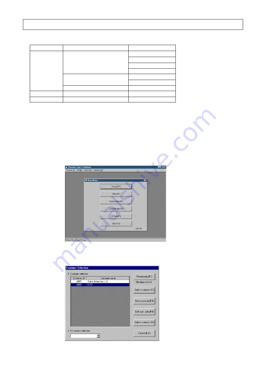
Procedures 

(1) Press the [Record(F1)] in the [Main menu] to display the window of the 

[Customer selection]. 


(2) In this window of the [Customer selection], input customer-related data.   

Recording data only without relating to customers is also possible. 


Содержание Service Checker TYPE 3.1

Страница 1: ... 0 SERVICE CHECKER TYPE 3 1 INSTRUCTION MANUAL Issued by Maintenance Sales Dep After Sales Service Div DAIKIN INDUSTRIES LTD 201210 ...

Страница 2: ... Setting of SS data 17 3 4 Setting of RS 232C COM port 17 3 5 Ending of TYPE 3 software 18 Chapter 4 Recording of operation data 19 4 1 Displaying of operation data 19 4 1 1 Selection of customer data and others 29 4 1 2 Displaying of network map 23 4 1 3 Inputting of detailed data 27 4 1 4 Displaying of operation data 29 4 2 Setting of recording 31 4 2 1 Setting of periodical recording in case of...

Страница 3: ...ioners It is a personal computer monitored device which is connected to an air conditioner and reads out operation data by temperature sensors pressure sensors several kinds of solenoid valves operating modes etc iv The Service Checker TYPE 3 1 is possible to measure six temperature measurement points and two pressure measurement points to monitor v The contents of the Manual are subject to change...

Страница 4: ...r TYPE 3 1 and the personal computer 4 Refer to the Chapter 3 Starting up and ending of TYPE 3 software on the starting up and ending of the TYPE 3 software and the setting of customer data and others 5 After connecting the Service Checker TYPE 3 1 to the air conditioner and the personal computer operation data and network map linking between an indoor unit and an outdoor unit can be displayed by ...

Страница 5: ...ice Checker TYPE 3 1 1 Service Checker TYPE 3 1 2 RS 232C cable D sub 9 pin female D sub 9 pin female straight 2m 3 USB cable A B connector cable 2m only for power supply DC 5V 2 TYPE 3 Software 2 Parts Number 999151T CD ROM software manual and information Caution Please always use the cable 2m originally attached to the Checker TYPE 3 1 Caution Please always use the cable 2m originally attached t...

Страница 6: ...vinyl cords or cables with two core and sheathed as follow Vinyl cabtyre cylindrical cord VCTF JISC3306 Vinyl insulated vinyl sheathed cable for control CVV JISC3401 Vinyl insulated vinyl sheathed cylindrical cable for control CVS JISC3401 Vinyl insulated vinyl sheathed cylindrical cable VVR JISC3342 600V vinyl cabtyre cable VCT JISC3312 Note Please do not use shielded cable Cautions 1 Do not use ...

Страница 7: ...nnector for power connection DC 5V Use USB cable originally attached to the Checker TYPE 3 1 Power switch When switching on the red lamp is lit Operating lamp When the Checker TYPE 3 is normally operated the green lamp is flashed Serial Connector Not use Parallel connector Not use Trigger Output Not use Sensor connector This connector is used for connecting the optional sensor kit Parts Number 999...

Страница 8: ...si V150 is version 1 2 Installing of Checker TYPE 3 software When the Service Checker TYPE 3 1 is newly purchased or the version up of the TYPE 3 software English is made install the new version of TYPE 3 software into the personal computer Note When the version up of the TYPE 3 software is made be sure to delete the old version in accordance with the procedures of the 1 2 Deleting of TYPE 3 softw...

Страница 9: ... 8 Chapter 1 Installing of TYPE 3 software 2 Select installation folder 3 Installing software 4 Complete ...

Страница 10: ... the procedures described below 1 Use Installer module 2 Use Control panel of Windows Procedures 1 Use Installer module Fallowing screen is displayed when the old version is already installed Please select Remove Daikin Service Checker Ver 1 xx 2 Using Control panel of Windows Click Add or Remove Programs Select checker TYPE3 software and remove it ...

Страница 11: ...units at the end of this Manual Note The range exceeding the limits of the DIII NET expansion adapter DTA109A1 is not possible to monitor To connect to the DIII NET terminals F1 F2 located on the PCB of an outdoor unit or an indoor unit Note In case of an indoor unit connect the end of the indoor unit not so as to create sub branching When the Service Checker TYPE 3 is connected to the DIII NET fo...

Страница 12: ... If wrongly connected to power terminals of centralized equipment and the like it may cause fatal injuries by electrical shock to human bodies and failures of equipment CAUTIONS 1 In case of connecting to an indoor unit connect the end of the indoor unit in consideration of not creating sub branching If sub branching is created communication errors may occur 2 Do not need to correspond F1 F2 of th...

Страница 13: ...nect air temperature thermistor for outdoor Th1 white Th2 Connect pipe temperature thermistor Th2 white Th3 Connect discharge pipe temperature thermistors Th3 red Since the discharge pipe temperature thermistors differs from other thermistors in a converting resistance value to temperature value method be sure to use the thermistor Th3 Th4 Connect pipe temperature thermistor Th4 blue HP Connect hi...

Страница 14: ...tting of records of TYPE 3 software Note In case of shifting Th5 to A or Th6 to V by using the switch of the Checker TYPE 3 shift at a screen before the screen of Display of network map otherwise operation data will not be correctly recorded 2 Set the sensor part to air conditioning systems When measuring current and voltage be sure to input a voltage signal of 0 5VDC or 0 1VDC via the measuring i...

Страница 15: ... 1 and the Serial connector of a personal computer RS 232C connector D sub 9 pin USB cable Power Supply connector 2 Connect the Power Supply PC AC adapter battery use USB cable Power Supply connector of the Checker TYPE 3 DC 5V 3 Turn on the Power Switch of the Checker TYPE 3 1 The red lamp of the Power Switch lights When the Checker TYPE 3 is normally operating the green lamp flashes Power Switch...

Страница 16: ... Play F2 Press when monitoring recorded operation data Refer to 5 1 Play of operation data Data transfer F3 Recorded operation data and customer data are transferred to a another folder Refer to 5 4 Data transfer Customer data F4 Customer data are input and edited Be sure to input customer ID Recorded network map data are possible to see here Refer to 3 2 Setting of customer data and 5 2 Playing b...

Страница 17: ... F4 in the Main menu to display the window of the Customer selection 2 When customer data are newly input press the New customer F3 to display the window of the next Input customer data When the current customer data need to be changed select the customer by cursor then press the Edit customer data F4 to display the window of the next Input customer data When customer data need to be deleted press...

Страница 18: ...F5 button When deleting select the name to be deleted by cursor before pressing the Delete F6 After completing the input press the Record F1 button When returning without recording press the Cancel ESC 3 4 Setting of RS 232C COM port The personal computer is equipped with the setting of RS 232C ports No COM1 to COM8 Default setting is COM1 Setup of PC MS Windows setting If changing the ports chang...

Страница 19: ...cording and playing back it is necessary to repeat several times pressing the Cancel ESC to return to the window of the Main menu In this case by pressing the button in the extreme upper right of the window the TYPE 3 software will end at once Example of the display of operation data 3 Also by selecting the End X of the menu of Function F located in the extreme upper left of the window the TYPE 3 ...

Страница 20: ...em 1 Mar 23 System 2 Mar 23 System 1 Feb 11 A building 1F System 1 Apr 2 A building 2F A customer B customer 4 1 Displaying of operation data 4 1 1 Selecting of customer data and others Procedures 1 Press the Record F1 in the Main menu to display the window of the Customer selection 2 In this window of the Customer selection input customer related data Recording data only without relating to custo...

Страница 21: ...oceeds to the Access Method selection Proceed to 5 Notes 1 In case of Record only be careful to note that operation data are overwritten every time 2 In case of recording customer data by the Record only in the DIII NET connection input customer data as much as possible since an air conditioner will be set to restart standby every time When deleting a customer data press the Delete customer F9 Whe...

Страница 22: ...K F1 by placing the cursor in the corresponding network map Proceed to the window of the Network Map Display Refer to 4 1 2 Network Map Display In case of being different network maps for DIII NET connected objects different DIII NET expansion adapter different PCB connected outdoor units for a customer with operation data recorded previously press the New F2 and proceed to the Access Method Selec...

Страница 23: ...rnal and external transmission method Possible to identify and select automatically the type of an air conditioner so selection is not necessary PCB connection do not use Sensor input only Select this when monitoring the temperature and pressure of an air conditioner in not conformity with DIII NET connection by an optional sensor kit c If the selection is OK press the O K F1 Proceed to the window...

Страница 24: ...by is allowed press the Yes F1 Notes 1 When pressing the Yes F1 air conditioners on the DIII NET are set to restart standby making the thermostat switched off for several minutes 2 If using the previous network data by customer management no such message in the window will be displayed again from the second time Then air conditioners on the DIII NET are automatically searched for several minutes N...

Страница 25: ...reful to note that Super Multi and room air conditioners connected to the PCB cannot be correctly displayed in distinguishing between an indoor unit and an outdoor unit 2 If nine or more indoor units are connected by using an expanding adapter for indoor units be careful to note that the display of operation data on the units is limited to on one indoor unit with average data 3 The system displaye...

Страница 26: ...ET are set to standby for restart making the thermostat switched off for several minutes Print screen F9 Press this button to print the screen of network map B Display mode F4 Display mode F4 Display operation data F6 Start DIIIdata recording F7 Display number of units F8 Display operation data F6 By proceeding to the window of Display operation data system operation data are displayed Proceed to ...

Страница 27: ...Set the periodical recording Proceed to the sections of 4 2 1 and 4 2 2 for periodical record setting Periodical record start F7 By pressing this button periodical record is started to indicate Periodical recording in red at the upper left in the window The indication of the button is changed to Periodical record end F7 Pressing the button again the periodical record is ended Trigger record settin...

Страница 28: ...me Input for a memo Model No Input for a memo Model name Since the automatic type identification in the DIII NET connection and the model name of the PCB connection input by following the window of the 5 Access Method Selection in the 4 1 1 Selecting of customer data and others are roughly designated model name select here the model name in detail After selected model name can be edited In case of...

Страница 29: ...accordance with the following procedures Auto address and Airnet address are not related to since they are automatically identified To correct the deviation move the detail data in accordance with the following procedures an example of transfer the detail data of In3 to In7 1 Select the In7 by the 1 Airconditioner selection in the window of the Detail data input 2 Press the List display F2 to disp...

Страница 30: ...right When at 100 full scale value is indicated The number and color of a graph coincide with those of at the left end in the data item in the window Eight items per an air conditioner can be displayed 2 Digital data ON OFF graph display left bottom in the window In case of ON blue bar is displayed The number of a graph coincides with that of the left end in the data item in the window Eight items...

Страница 31: ...m of an indoor unit connected to the PCB Internal and external transmission error shows the state that due to an indoor unit s error signal transmission between an indoor unit and an outdoor unit cannot be performed Indoor unit error shows the error state that it is impossible for an indoor unit to switch thermostat ON System error shows that the overall system between an indoor unit and an outdoo...

Страница 32: ... data ON OFF The TYPE 3 software can set the method separately Sensor input can be set only in the periodical recording Periodical record start Periodical record 4 2 1 4 2 2 Trigger inspection start Meeting trigger conditions Time Trigger record 4 2 3 4 2 1 Setting of periodical recording in case of DIII NET connection The window of the Periodical record setting is displayed by pressing the button...

Страница 33: ...ls of several minutes in case of indoor units 2 Recording end method Set a recording stop method as follows Manual In the window of the Network Map Display continue to record until pressing the Periodical record stop F7 button Automatic Recording of operation data ends automatically after arriving at a pre set recording time Input a recording time with a minute unit 3 Recording system selection 1 ...

Страница 34: ...be used 2 Input the Item name for recording data Th5 Th6 1 Click with the mouse the Check box at the left of sensor connectors to be used 2 Input the Item name for recording data 3 If the switch of the Checker TYPE 3 is positioned at A or V set further the items located at the right side in the window a Select the range of voltage signals with 0 5VDC or 0 1VDC b Input a value at 0 V in the item of...

Страница 35: ...dical record start F7 in the window of the Network Map Display to display the Periodical recording in red at the upper left in the window Also the indication of the button is changed to the Periodical record end F7 5 When ending the Periodical record manually press the Periodical record end F7 If in the Recording end method of the Automatic is set recording data is automatically ended after pre se...

Страница 36: ... periodical recording in case of DIII NET connection and PCB connection There is no setting of the 3 Recording system selection 2 Set the 4 Setting of sensor input Refer to 2 of the 4 2 1 Setting of periodical recording in case of DIII NET connection and PCB connection 3 When completing to set the above press the Setting complete F1 to return to the window of the Network Map Display 4 When startin...

Страница 37: ... of operation data 5 When ending the periodical recording manually press the Periodical record end F7 If in the Recording end method of 1 the Automatic is set recording data is ended automatically after pre set recording time ...

Страница 38: ...by pressing the button of the Trigger record setting F8 after selecting the Recording mode F5 in the window of the Network Map Display The window of Trigger record setting Procedures 1 Set the 1 Record time before and after trigger and the 2 Trigger setting Setting item Description 1 Record time before and after trigger When the trigger conditions are met in the window of the 2 2 Trigger condition...

Страница 39: ...selection window and the Free hard disk area KB at the bottom of the window are displayed confirm if the free area is enough in recording the data However be careful to note that if the free hard disk area of the personal computer is more than 2 GB values may not be displayed correctly 2 Press the Setting complete F1 to return to the Network Map Display 3 When starting the trigger record inspectio...

Страница 40: ...possible From the next time the centralized operation can be performed without setting the centralized address by using both customer data obtained this time and the network map without setting of centralized adress The window of the Centralized operation is displayed by pressing the button of the Centralized operation F7 after selecting the Map mode F3 in the window of the Network Map Display The...

Страница 41: ...er Fan F9 Issue fan mode command to air conditioner Error code If error occurs display error code Right side in the window Same statement as remote controller is displayed with red characters in the right side in the window Under Center Control Not possible to operate from Checker Under Forced Stop Not possible to operate from Checker other than stop Under Centralized Control If other centralized ...

Страница 42: ...omer Data Selection is displayed below Place the cursor in the target operation data Operation data display F1 The operation data are displayed Proceed to 3 Trigger condition display F2 In case of operation data recorded by the Trigger recording the setting of the trigger recording at that time is displayed CSV data output F3 The data of CSV format possible to be read by commercial integrated soft...

Страница 43: ... graph is moved to the left in the window Forward F4 A graph is moved to the right in the window Left F5 The cursor on a graph is moved to the left in the window Right F6 The cursor on a graph is moved to the right in the window Print screen F9 Screen is printed 4 The maximum and minimum analog data and error code can be searched Digital data cannot be searched Press the Search F7 button by placin...

Страница 44: ...rom the top F1 Searching is made from the top of operation data Search next F2 Searching is made in the direction from a cursor position on a graph to time lapse Cancel ESC Returning to the window of the Operation Data Display 5 Press the Cancel ESC button to return to the window of the Customer Data Selection ...

Страница 45: ...u to display the window of the Customer Selection 2 The window of the Customer Selection is displayed below Press the Select customer F2 to display the window of the Network Map Selection 3 The window of the Network Map Selection is displayed below By placing the cursor in the target name of the network map press the OK F1 button to proceed the window of the Network Map Display ...

Страница 46: ...play is displayed below UP F1 Down F2 The window is scrolled upward and downward respectively Detail data input F6 The detail data of an air conditioner designated by cursor are displayed Print screen F9 Screen is printed Cancel ESC Return to the window of the Network Map Selection ...

Страница 47: ...tegrated software are output Procedures 1 Press the Play F2 in the Main Menu to display the window of the Customer Data Selection 2 The window of the Customer Data Selection is displayed below Press the CSV data output F3 to display the window of the Save with file name 3 CSV file output setting set output date and header data ...

Страница 48: ...e has become bigger because of being recorded for a long time and resultantly the integrated application software can not read in by one file the file may be divided into multiple files automatically Estimated time in CSV data processing In the DIII NET connection if one outdoor unit and eight indoor units are periodically recorded at intervals of 5 seconds for 3 8 days the file size of the operat...

Страница 49: ...ed the TYPE 3 software fixed The right in the window is a destination of transfer The Drive name and the Folder name directory name can be changed The unit of data transfer consists of two 1 Operation data and Customer data and 2 only Customer data The data of network map are included in the customer data 1 Transferring operation data and customer data A In case of transferring data from the hard ...

Страница 50: ...a and customer data C If the operation data with the same title already exists the following window is displayed Yes F1 Only this operation data is overwitten Overwrite all F2 All the operation data after this are overwitten No F3 While not overwriting this operation data the next operation data are successively being transferred Cancel ESC Data transfer is stopped D If the customer data with the ...

Страница 51: ...eive voltage signals 0 to 5VDC or 0 to 1VDC Standard configuration Product name Part number Description Checker TYPE 3 1 1 Service Checker TYPE3 1 2 RS 232C cable for personal computers D sub 9 pin female D sub 9 pin female straight 2m shield cable 3 USB cable A type B type 2m shield cable TYPE3 Software2 999151T Software for English version Windows and this manual Option parts Product name Part n...

Страница 52: ...cations are valid as of Nov 2012 and they may be modified for improvement without any advance notice For any inquiries please contact the following division DAIKIN INDUSTRIES LTD Engineering Information Sect Planning Dept After Sales Service Div Umeda Center Bldg 2 4 12 Nakazaki Nishi Kita Ku Osaka 530 Japan Phone 06 374 9373 FAX 06 373 4382 Daikin Europe N V Zandvoordestraat 300 B 8400 Oostende B...

Отзывы: