background image

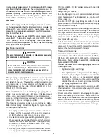
25

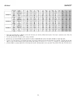
Model

Minimum Recommended  Filter Size^

DM96SE0403BU*

1 - 16 X 25 Side or Bottom

DM96SE0603BU*

1 - 16 X 25 Side or Bottom

DM96SE0805BU*

1 - 20 X 25 Bottom / 2 - 16 X 25 Side Return

Filter Sizing Chart

^ Larger filters may be used, filters may also be centrally located

Change filters before occupants take ownership of a new home.

Consider installing an air cleaner with deep-pleated media
filter at the time of furnace installation. A deep-pleated fil-
ter with a MERV rating of 8 (minimum) will often provide
better filtration to protect equipment and the air distribu-
tion system than a standard 1" filter and often has lower
static pressure loss than a 1" filter. Also a deep-pleated filter
will typically require less frequent replacement intervals. Avoid
using highly restrictive 1" filters which produce static pres-
sure loss greater than .25" W.C. In some installations the
minimum filter size required (consult filter sizing chart on
page 34) will not lend itself to a filter installation on the side
of the furnace. The installation of a centrally installed air
cleaner cabinet or a return duct filter installation may offer
more practicality.

Clean Comfort™ brand MERV 11 air cleaners have 5¼” media
filters and are available in the following configurations. Con-
sult your distributor for information on our complete line of
IAQ Clean Comfort™ products.

Air Cleaner

Installation Location

Maximum

Heating Airflow

Filter (Media)

Dimensions

Part Number

Air Cleaner 

Family

Side or bottom return

1200 CFM

16 in X 20 i n x 5¼"

AM11-1620-5

Side or bottom return

1600 CFM

16 in X 25 i n x 5¼"

AM11-1625-5

Side or bottom return

1600 CFM

20 in X 20 i n x 5¼"

AM11-2020-5

Side or bottom return

2000 CFM

20 in X 25 i n x 5¼"

AM11-2025-5

Side return

(for 2 sepa ra te returns)

Side return (Ri ght a ngl e)

2000 CFM

20 in X 25 i n x 5¼"

AM11-2025-5RA

AM11-5RA

Bottom return (pl a tform)

2000 CFM

20 in X 25 i n x 5¼"

AM11-2832-5PP

Bottom return (pl a tform)

2000 CFM

20 in X 25 i n x 5¼"

AM11-2843-5PP

AM11-5

2 X 1600 CFM

2, 16 in X 25 i n x 5¼"

AM11-3225-5

AM11-3225

AM11-5PP

AM11-5

AM11-5RA

AM11-5PP

Family

Family

Family

U

PRIGHT

 I

NSTALLATIONS

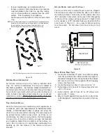
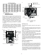
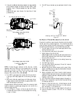
Depending on the installation and/or customer preference,
differing filter arrangements can be applied.  Filters can be
installed in the central return register or a side panel exter-
nal filter rack kit (upflows).  As an alternative a media air
filter or electronic air cleaner can be used as the requested
filter.

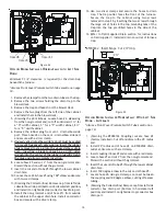
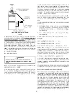
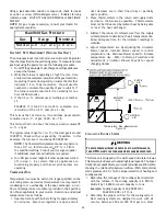
CUT FOUR CORNERS
AFTER REMOVING SHEET
METAL


CUT USING TIN SNIPS

PRESS OUT BY HAND

SCRIBE LINES OUTLINING
DUCT FLANGES

Duct Flange Cut Outs

Figure 30

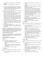
When the furnace is used in connection with a cooling unit, the
furnace should be installed in parallel with or on the upstream
side of the cooling unit to avoid condensation in the heating
element.  With a parallel flow arrangement, the dampers or
other means used to control the flow of air must be adequate
to prevent chilled air from entering the furnace and, if manu-
ally operated, must be equipped with means to prevent opera-
tion of either unit unless the damper is in the full heat or cool
position.

When the furnace is installed without a cooling coil, it is rec-
ommended that a removable access panel be provided in the
outlet air duct.  This opening shall be accessible when the
furnace is installed and shall be of such a size that the heat
exchanger can be viewed for visual light inspection or such
that a sampling probe can be inserted into the airstream.  The
access panel must be made to prevent air leaks when the
furnace is in operation.

When the furnace is heating, the temperature of the return air
entering the furnace must be between 55°F and 100°F.

F

ILTERS

 - R

EAD

 T

HIS

 S

ECTION

 B

EFORE

 I

NSTALLING

 T

HE

 R

ETURN

A

IR

 D

UCT


WORK

Filters must be used with this furnace. Discuss filter mainte-
nance with the building owner.  Filters do not ship with this
furnace, but must be provided, sized and installed externally
by the installer. Filters must comply with UL900 or CAN/
ULCS111 standards. Damage or repairs due to the installa-
tion of the furnace without filters are not covered under
the warranty.

On upflow units, guide dimples locate the side return cutout
locations.  Use a straight edge to scribe lines connecting the
dimples.  Cut out the opening on these lines.  

NOTE:

 An under-

sized opening will cause reduced airflow.

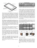
Refer to the Filter Sizing Chart to determine filter area re-
quirements.

Содержание DM96SE

Страница 1: ... BEEN TRAINED TO INSTALL ADJUST SERVICE OR REPAIR HEREINAFTER SERVICE THE EQUIPMENT SPECIFIED IN THIS MANUAL SHOULD SERVICE THE EQUIPMENT THE MANUFACTURER WILL NOT BE RESPONSIBLE FOR ANY INJURY OR PROPERTY DAMAGE ARISING FROM IMPROPER SERVICE OR SERVICE PROCEDURES IF YOU SERVICE THIS UNIT YOU ASSUME RESPONSIBILITY FOR ANY INJURY OR PROPERTY DAMAGE WHICH MAY RESULT IN ADDITION IN JURISDICTIONS THAT...

Страница 2: ...T INSTALLATIONS 25 HORIZONTAL INSTALLATIONS 26 DRAIN TRAP PRIMING 26 FURNACE OPERATION 26 GAS SUPPLY PRESSURE MEASUREMENT 26 GAS MANIFOLD PRESSURE MEASUREMENT AND ADJUSTMENT 27 GAS INPUT RATE MEASUREMENT NATURAL GAS ONLY 28 TEMPERATURE RISE 28 CIRCULATOR BLOWER SPEEDS 28 BLOWER HEAT OFF DELAY TIMINGS 29 NORMAL SEQUENCE OF OPERATION 29 POWER UP 29 HEATING MODE 29 COOLING MODE 29 FAN ONLY MODE 29 OP...

Страница 3: ...PROPER INSTALLATION ADJUSTMENT ALTERATION SERVICE OR MAINTENANCE REFER TO THIS MANUAL FOR ADDITIONAL ASSISTANCE OR INFORMATION CONSULT A QUALIFIED INSTALLER SERVICER AGENCY OR THE GAS SUPPLIER WARNING IF THE INFORMATION IN THESE INSTRUCTIONS IS NOT FOLLOWED EXACTLY A FIRE OR EXPLOSION MAY RESULT CAUSING PROPERTY DAMAGE PERSONAL INJURY OR LOSS OF LIFE DO NOT STORE OR USE GASOLINE OR OTHER FLAMMABLE...

Страница 4: ...ar a través del aparato cuando se opera en cualquier modo B10259 216 RISQUE D EMPOISONNEMENT AU MONOXYDE DE CARBONE Le monoxyde de des carbone peut causer des maladies graves telles que dommages permanents au cerveau et meme la mort Cette ventilation est nécessaire pour éviter le danger d intoxication au CO pouvant survenir si un appareil produisant du monoxyde de carbone continue de fonctionner a...

Страница 5: ... burners through a special air intake system outlined in these instructions This furnace cannot be used as a construction site heater To ensure proper furnace operation install operate and maintain the furnace in accordance with these installation and operation instructions all local building codes and or dinances In their absence follow the latest edition of the National Fuel Gas Code NFPA 54 ANS...

Страница 6: ...ematureheatexchangerfailurewill resultifthecoolingunitisplacedaheadofthefurnace For vertical upflow or downflow applications the minimum cooling coil width shall not be less than furnace width minus 1 Additionally a coil installed above an upflow furnace may be the same width as the furnace or may be one size larger than the furnace Example a C width coil may be installed with a B width furnace Fo...

Страница 7: ...e ANSI Z223 1 NFPA 54 9 After it has been determined that each appliance connected to the venting system properly vents when tested as outlined above return doors windows exhaust fans fireplace dampers and any other gas burning appliance to their previous conditions of use If resizing is required on any portion of the venting system use the appropriate table in Appendix G in the latest edition of ...

Страница 8: ...PENSION If suspending the furnace from rafters or joists use 3 8 threaded rod and 2 x2 x1 8 angle iron as shown in the fol lowing diagram The length of rod will depend on the applica tion and the clearances necessary If the furnace is installed in a crawl space it must be sus pended from the floor joist or supported by a concrete pad Never install the furnace on the ground or allow it to be ex pos...

Страница 9: ...nts of another manufac turer All furnaces are manufactured with 2 vent intake pipe and connectors For furnaces requiring installation of 3 pipe the transition from 2 to 3 should be done as close to the furnace as practically possible This furnace must not be connected to Type B BW or L vent or vent connector and must not be vented into any portion of a factorybuiltormasonrychimneyexceptwhenusedasa...

Страница 10: ... the manufacturer s instructions for cutting cleaning and solvent cementing of PVC The use of Schedule 40 PVC cellular core DWV meeting ASTM F891 1 or ABS cellular core Foam Core plastic pipe is also acceptable as a flue vent and intake pipe material PVC primer meeting ASTM F656 and PVC sol vent cement meeting ASTM D2564 specifications must be used Fittings must be DWV type fittings meeting ASTM D...

Страница 11: ...termination of a direct vent application Theventterminationofanon directventapplicationmust terminate at least 4 feet below 4 feet horizontally from or 1 foot above any door window or gravity air inlet into any building The vent termination of a direct vent application must terminate at least 12 inches from any opening through which flue gases may enter a building door window or gravity air inlet ...

Страница 12: ...tube can serve as a trap The unused RF000142 drain fitting should be capped Figure 8B A tee installed in the intake pipe is also an acceptable method of catching condensation It must have a field supplied trapped drain tube or pipe free draining to proper condensate disposal location A loop in the drain tube can serve as a trap Insert flange Cut 2 long RF000142 2 Figure 9 THE RUBBER ELBOW IS NOT D...

Страница 13: ...weentheventpipeandthe chimney must be closed with a weather tight corrosion resis tant flashing Although non direct vent installations do not require a com bustion air intake pipe a minimum of one 90 elbow should be attached to the furnace s combustion air intake if an up right installation uses the standard intake location or a hori zontal installation uses the alternate air intake location This ...

Страница 14: ...E BETWEEN INTAKE AND VENT 12 MIN TO ROOF OR HIGHEST ANTICIPATED SNOW LEVEL Figure 12 Figure 11 Floor Use alternate vent combination air locations DOWN VENTING UPFLOW MODEL FURNACES ONLY Basement Crawlspace Condensate trapped to prevent flue gas from escaping and routed to field supplied condensate disposal Combustion Air Pipe Vent Pipe All piping and fittings must be joined per material manufactur...

Страница 15: ...me atmospheric pressure zone Refer to Vent Flue and Combustion Air Pipe Termination Locations or Concen tric Vent Termination for specific details on termination con struction For details concerning connection of pipes to the furnace refer to the Vent Flue Pipe and Combustion Pipe Standard Furnace Connections or Alternate Furnace Connec tions 90º OR 45 ELBOW 12 MIN TO GRADE OR HIGHEST ANTICIPATED ...

Страница 16: ... TERMINATION Refer to the directions provided with the Concentric Vent Kit DCVK for installation specifications Ve rtical Installation H orizontal Installation Side Wall Vent Kit Figure 19 SIDE WALL VENT KIT This kit is to be used with 2 or 3 direct vent systems The vent kit must terminate outside the structure and may be in stalled with the intake and exhaust pipes located side by side or with on...

Страница 17: ...the drain trap to be removed for cleaning The drain trap must be primed before initial furnace start up When an air conditioning coil drain is connected to the field supplied furnace drain it must be vented by an open tee installed at a height no higher than the bottom of the furnace col lector box to prevent air conditioning condensate from backing up into the furnace if the common drain was bloc...

Страница 18: ...e front of the furnace Secure the trap to the cabinet using two screws removed in step 2 by inserting the two screws through the large set of holes in the top mounting tabs of the trap into the two predrilled holes in the side of the cabinet 8 Refer to Field Supplied Drain section for instructions on field supplied installed drain on outlet of furnace trap DRAIN EXITING LEFT SIDE 1 Install the 45 ...

Страница 19: ...L INSTALLED HORIZONTALLY WITH LEFT SIDE DOWN Minimum 5 1 2 clearance is required for the drain trap beneath the furnace Also see Front Cover Pressure Switch Tube Location on page 10 1 Remove the clamps from the two drain tubes on the trap 2 Remove the two screws holding the drain trap to the blower deck 3 Remove the trap and hoses from the blower deck 4 Remove the two plugs from the left side of t...

Страница 20: ...pecified on the unit rating plate An electrical disconnect must be provided at the furnace location Connect hot neutral and ground wires as shown in the wir ing diagram located on the unit s blower door For direct vent applications the cabinet opening to the junction box must be sealed air tight using either an UL approved bushing such as Heyco Liquid Tight or by applying non reactive UL approved ...

Страница 21: ...CAL SHOCK WIRING TO THE UNIT MUST BE POLARIZED AND GROUNDED WARNING HIGH VOLTAGE TO AVOID PERSONAL INJURY OR DEATH DUE TO ELECTRICAL SHOCK DISCONNECT ELECTRICAL POWER BEFORE SERVICING OR CHANGING ANY ELECTRICAL WIRING WARNING LABEL ALL WIRES PRIOR TO DISCONNECTION WHEN SERVICING CONTROLS WIRING ERRORS CAN CAUSE IMPROPER AND DANGEROUS OPERATION VERIFY PROPER OPERATION AFTER SERVICING CAUTION Line v...

Страница 22: ...old or gas valve Useblackironorsteelpipeandfittingsforbuildingpiping Wherepossible usenewpipethatisproperlychamfered reamed and free of burrs and chips If old pipe is used be sure it is clean and free of rust scale burrs chips and old pipe joint compound Use pipe joint compound on male threads ONLY Always use pipe joint compound pipe dope that is APPROVED FOR ALL GASSES DO NOT apply compound to th...

Страница 23: ...dard Gas Line Hole Drip Leg Burners Manifold NOTE Union may be inside furnace cabinet where allowed by local codes UPFLOW Figure 27 Manual Shut Off Valve upstream from ground joint pipe union Drip Leg Plug in Alternate Gas Line Hole Grommet in Standard Gas Line Hole Alternate Union Location Burners Drain Trap Gas Valve Plug in Main Gas Line Hole Manifold UPFLOW HORIZONTAL LEFT Figure 28 GAS PIPING...

Страница 24: ...ne total external duct static pressure proceed as follows 1 With clean filters in the furnace use a draft gauge inclined manometer to measure the static pressure of the return duct at the inlet of the furnace Nega tive Pressure 2 Measure the static pressure of the supply duct Posi tive Pressure 3 The difference between the two numbers is 4 w c Example static reading from return duct 1 w c static r...

Страница 25: ...NSTALLATIONS Depending on the installation and or customer preference differing filter arrangements can be applied Filters can be installed in the central return register or a side panel exter nal filter rack kit upflows As an alternative a media air filter or electronic air cleaner can be used as the requested filter CUT FOUR CORNERS AFTER REMOVING SHEET METAL CUT USING TIN SNIPS PRESS OUT BY HAN...

Страница 26: ... try to light the burner by hand 5 Move the furnace gas valve manual control to the OFF position 6 Wait five minutes then smell for gas Be sure check near the floor as some types of gas are heavier than air 7 If you smell gas after five minutes immediately follow the Safety Considerations section of this manual If you do not smell gas after five minutes move the furnace gas valve manual control to...

Страница 27: ...With Fitting Manometer Hose Manometer Open To Atmosphere Measuring Inlet Gas Pressure Alt Method Figure 34 GAS MANIFOLD PRESSURE MEASUREMENT AND ADJUSTMENT Only small variations in gas pressure should be made by adjust ing the gas valve pressure regulator The manifold pressure must be measured with the burners operating To measure and adjust the manifold pressure use the following procedure 1 Turn...

Страница 28: ... TEMPERATURE RISE Temperature rise must be within the range specified on the unit rating plate An incorrect temperature rise may result in condensing in or overheating of the heat exchanger An air flow and temperature rise table is provided in the Specifica tion Sheet applicable to your model Determine and adjust temperature rise as follows 1 Operate furnace with burners firing for approximately t...

Страница 29: ...m thermostat HEATING MODE The normal operational sequence in heating mode is as fol lows R and W thermostat contacts close initiating a call for heat Integrated control module performs safety circuit checks Induced draft blower is energized for a 15 second prepurge Igniter warm up begins upon presence of closed pressure switch contacts Gas valve opens at end of igniter warm up period delivering ga...

Страница 30: ...ustion air and flue products through the heat exchanger and or blocked condensate drain condi tions FLAME SENSOR The flame sensor is a probe mounted to the burner manifold assembly which uses the principle of flame rectification to determine the presence or absence of flame PRESSURE SENSOR Pressure sensor is mounted on the induced draft blower Its function is to regulate the induced draft blower s...

Страница 31: ...y a qualified installer or service agency at least once per year This check should be performed at the beginning of the heating season This will ensure that all furnace components are in proper working order and that the heating system functions appropriately Pay particular attention to the following items Repair or service as necessary Flue pipe system Check for blockage and or leakage Check the ...

Страница 32: ...e flame and will lock out The flame sensor should be carefully cleaned by a qualified servicer using emery cloth or steel wool Following cleaning the flame sense signal should be as indi cated in the Specifications Sheet FLUE PASSAGES QUALIFIED SERVICER ONLY The heat exchanger flue passageways should be inspected at the beginning of each heating season BEFORE LEAVING AN INSTALLATION Cycle the furn...

Страница 33: ...nues to attempt to start furnace and fault is displayed until fault condition corrects or CFH is removed 4 Flashes High Limit Switch Open RED When an open limit is detected the control energizes the blower at cooling speed and the inducer at the RUN setting no CFH required Once the limit closes and the CFH is present the furnace returns to normal operation Three limit events in a single CFH result...

Страница 34: ...ss and hold the SW1 button for more than 5 seconds results in the display of this mode Releasing the Button during this indication will cause the Error History to be cleared The button must be released within 5 seconds after the LED begins this flash sequence 3 Rapid Flashes On reset ONLY ID Plug Installed GREEN For controls with unit specific programming imbedded in the CPU this indicates at powe...

Страница 35: ...0 2 Rise 0 3 Rise 0 4 Rise 0 5 Rise 0 6 0 7 0 8 Red High Cool 3 1350 NA 1310 NA 1273 NA 1234 NA 1198 NA 1156 1117 1078 Blue MedHi Heat 2 5 1247 29 1212 30 1167 31 1129 32 1087 33 1043 997 952 Brown MedLow 2 1151 31 1107 32 1067 35 1021 35 977 36 928 880 835 Black Low 1 5 922 39 870 41 819 43 763 47 704 51 643 592 539 Orange FanOnly 1 779 46 661 54 588 NA 516 NA 455 NA 394 352 N A Red High Cool 3 1...

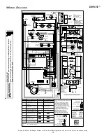
Страница 36: ...EVICE OVERCURRENT FIELD GND EQUIPMENT GND JUNCTION INTEGRATED CONTROL INTERNAL TO 0140F02069 C 2 MANUFACTUR S SPECIFIED REPLACEMENT PARTS MUST BE USED WHEN SERVICING 1 SET HEAT ANTICIPATOR ON ROOM THERMOSTAT AT 0 7 AMPS NOTES HI VOLTAGE FIELD HI VOLTAGE 115V LOW VOLTAGE FIELD LOW VOLTAGE 24V COLOR CODES RD RED GY GRAY BL BLUE WH WHITE BR BROWN BK BLACK GN GREEN PU PURPLE OR ORANGE YL YELLOW WH SEN...

Страница 37: ...37 THIS PAGE LEFT INTENTIONALLY BLANK ...

Страница 38: ...38 THIS PAGE LEFT INTENTIONALLY BLANK ...

Страница 39: ...39 THIS PAGE LEFT INTENTIONALLY BLANK ...

Страница 40: ...se register by following this link https daikincomfort com owner support product registration You can also scan the QR code on the right to be directed to the Product Registration page CUSTOMER FEEDBACK Daikin is very interested in all product comments Please fill out the feedback form on the following link https daikincomfort com contact us You can also scan the QR code on the right to be directe...

Отзывы: