


17
•
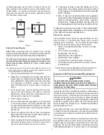
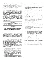
If an air conditioning coil is installed with the
furnace, a common drain may be used. An open tee
must be installed in the drain line, near the cooling
coil, to relieve positive air pressure from the coil’s
plenum. This is necessary to prohibit any
interference with the function of the furnace’s drain
trap.
NOTE:
In vertical installations, air conditioning coil condensate may
drain into the furnace trap as long as there is a trap between
the coil and the furnace trap and the drain pipe is not
terminating below the water level of the furnace trap.
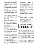
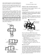
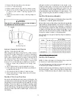
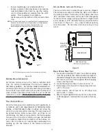
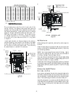
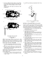
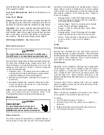
#3
#1
#2
#4
#5
#6
#7
#8
#9
#10
#11
100 Degree
Elbow
Coupling
NOTE:
Drain components shown for information purposes only.
Figure 20
G
ENERAL
D
RAIN
I
NFORMATION
All furnace models come with a factory installed drain
trap. For vertical installations, the trap will
remain in
the factory position. All furnace models installed
hori-
zontally require the trap to be relocated. Many drain hoses
have a built–in grommet which will provide a cabinet seal
when installed. See instructions below for your model and
installation position.
NOTE: Both sides of the drain trap
must be primed prior to initial furnace start up
F
IELD
S
UPPLIED
D
RAIN
Drain the furnace and air conditioning coil if applicable, in
compliance with code
requirements. In horizontal instal-
lations, a field installed
rubber coupling will allow the
drain trap to be removed for cleaning. The drain trap must
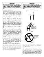
be primed before initial furnace start up. When an air
conditioning coil drain is connected to the field supplied
furnace drain, it must be vented by an open tee installed
at a height no higher than the bottom of the furnace col-
lector box to prevent air conditioning condensate from
backing up into the furnace if the common drain was
blocked.
U
PFLOW
M
ODEL
I
NSTALLED
V
ERTICALLY
The trap and factory installed hoses remain as shipped.
The furnace drain may exit either the right or left side of
the furnace cabinet. Both sides of the cabinet have two
.875” diameter holes which can be used interchangeably
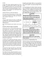
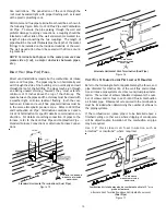
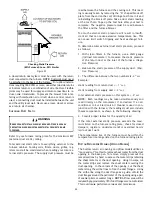
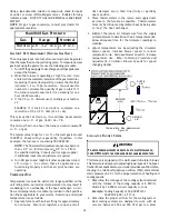
for drain and low voltage wiring purposes. If a higher drain
exit is needed, a .875” diameter hole may be added in the
area shown in Figure 21. Any unused cabinet opening
must be sealed. Do not allow drain hose to sag or trap
water.
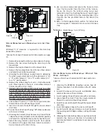
Side Cut-Out
12”
3”
Right side shown.
Acceptable
area for
drain hole.
Figure 21
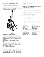
D
RAIN
E
XITING
R
IGHT
S
IDE
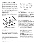
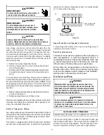
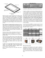
1. Locate and Install the 45º pipe / hose drain coupling
from the outside of the cabinet (barbed end goes in
the cabinet) through hole in the right side of the cabinet
and secure with two field supplied #8 self-tapping
screws (see Figure 22).
2. Locate the long drain hose #3 and cut at line “A” .
3. Install large end of hose #3 to trap outlet and secure
with 1.25" clamp.
4. Install smaller end of hose #3 on 45º elbow and
secure with 1" clamp.
5. Refer to Field Supplied Drain section for instructions
on field supplied / installed drain on outlet of furnace
trap.
Содержание DM96SE
Страница 37: ...37 THIS PAGE LEFT INTENTIONALLY BLANK ...
Страница 38: ...38 THIS PAGE LEFT INTENTIONALLY BLANK ...
Страница 39: ...39 THIS PAGE LEFT INTENTIONALLY BLANK ...


