21
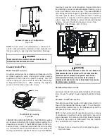
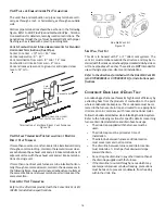
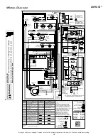
located on the blower compartment door, for further details
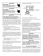
of 115 Volt and 24 Volt wiring.
R
Y
C
Furnace Integrated
Control Module
Remote Condensing Unit
(Single-Stage Cooling)
R
Room
Thermostat
Figure 26
S
INGLE
-S
TAGE
H
EATING
T
HERMOSTAT
A
PPLICATION
A single-stage thermostat with only one heating stage is
needed to control this furnace.
F
OSSIL
F
UEL
A
PPLICATIONS
This furnace can be used in conjunction with a heat pump in a
fossil fuel application. A fossil fuel application refers to a
combined gas furnace and heat pump installation which uses
an outdoor temperature sensor to determine the most cost
efficient means of heating (heat pump or gas furnace).
Strictly follow the wiring guidelines in the fossil fuel kit in-
stallation instructions. All furnace connections must be made
to the furnace integrated control module and the “FURNACE”
terminal strip on the fossil fuel control board.
G
AS
S
UPPLY
AND
P
IPING
WARNING
P
OSSIBLE
PROPERTY
DAMAGE
,
PERSONAL
INJURY
OR
DEATH
MAY
OCCUR
IF
THE
CORRECT
CONVERSION
KITS
ARE
NOT
INSTALLED
. T
HE
APPROPRIATE
KITS
MUST
BE
APPLIED
TO
ENSURE
SAFE
AND
PROPER
FURNACE
OPERATION
. A
LL
CONVERSIONS
MUST
BE
PERFORMED
BY
A
QUALIFIED
INSTALLER
OR
SERVICE
AGENCY
.
T
O
AVOID
POSSIBLE
UNSATISFACTORY
OPERATION
OF
EQUIPMENT
DAMAGE
DUE
TO
UNDERFIRING
OR
EQUIPMENT
,
USE
THE
PROPER
SIZE
OF
NATURAL
GAS
PIPING
NEEDED
WHEN
RUNNING
PIPE
FROM
THE
METER
/
TANK
TO
THE
FURNACE
.
WARNING
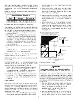
Natural Gas
Minim um : 4.5" w.c. Maxim um : 10.0" w.c.
INLET GAS SUPPLY PRESSURE
The furnace rating plate includes the approved furnace gas
input rating and gas types. The furnace must be equipped to
operate on the type of gas applied. This includes any conver-
sion kits required for alternate fuels and/or high altitude.
HIGH VOLTAGE !
T
O
AVOID
THE
RISK
OF
ELECTRICAL
SHOCK
,
WIRING
TO
THE
UNIT
MUST
BE
POLARIZED
AND
GROUNDED
.
WARNING
HIGH VOLTAGE !
T
O
AVOID
PERSONAL
INJURY
OR
DEATH
DUE
TO
ELECTRICAL
SHOCK
,
DISCONNECT
ELECTRICAL
POWER
BEFORE
SERVICING
OR
CHANGING
ANY
ELECTRICAL
WIRING
.
WARNING
L
ABEL
ALL
WIRES
PRIOR
TO
DISCONNECTION
WHEN
SERVICING
CONTROLS
. W
IRING
ERRORS
CAN
CAUSE
IMPROPER
AND
DANGEROUS
OPERATION
. V
ERIFY
PROPER
OPERATION
AFTER
SERVICING
.
CAUTION
Line voltage connections can be made through either the
right or left side panel. The furnace is shipped configured
for a left side electrical connection. To make electrical con-
nections through the opposite side of the furnace, the junc-
tion box must be relocated to the right side prior to making
electrical connections. To relocate the junction box, perform
the following steps.
1. Remove the burner compartment door.
2. Remove and save the two screws securing the junction
box to the side panel.
3. Relocate junction box and associated plugs and grommets
to opposite side panel. Secure with screws removed in
step 2.
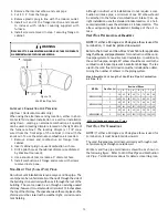
To ensure proper unit grounding, the ground wire should run
from the furnace ground screw located inside the furnace junc-
tion box all the way back to the electrical panel.
NOTE:
Do not
use gas piping as an electrical ground. To confirm proper unit
grounding, turn off the electrical power and perform the follow-
ing check.
1. Measure resistance between the neutral (white) connection
and one of the burners.
2. Resistance should measure 10 ohms or less.
This furnace is equipped with a blower door interlock switch which
interrupts unit voltage when the blower door is opened for ser-
vicing. Do not defeat this switch.
24 V
OLT
T
HERMOSTAT
W
IRING
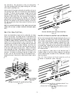
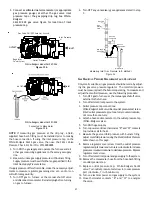
Low voltage connections can be made through either the right or
left side panel. Thermostat wiring entrance holes are located in
the blower compartment. The following figure shows connec-
tions for a “heat/cool system”.
This furnace is equipped with a 40 VA transformer to facilitate
use with most cooling equipment. Consult the wiring diagram,
Содержание DM96SE
Страница 37: ...37 THIS PAGE LEFT INTENTIONALLY BLANK ...
Страница 38: ...38 THIS PAGE LEFT INTENTIONALLY BLANK ...
Страница 39: ...39 THIS PAGE LEFT INTENTIONALLY BLANK ...

