background image

35

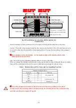
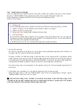
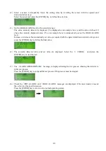
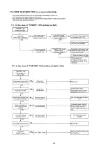
(2) Select a sensor to temporarily lower the setting value by scrolling the screen with the upward and

downward arrow keys.
Select the sensor and press the [ENTER] key to define the selection.

(3) Set the HIGH ALARM level for the selected sensor.

The value currently detected is displayed (5 is displayed as an example here), and the value of about 10
above the currently displayed value (15 as an example here) is automatically set as the HIGH ALARM
level.
Increase or decrease the automatically set value as required with the upward and downward arrow keys and
press the [ENTER] key to define the final value.

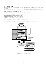
(4) The currently detected value and set value are displayed. Select the

1. CHECK

and press the

[ENTER] key to start the test.

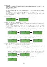
(5) The

ALARM OPERATION OK

message is displayed during the test process, showing the detector is

in the test process.
Press the [ENTER] key to suspend the test process if the process must be stopped.

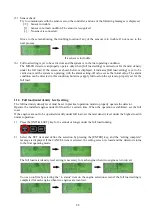
(6) Check the

PRE ALARM

and

HIGH ALARM

messages are displayed if the mist density exceeds

the set level at the specified sensor.
Press the [ENTER] key to return to the normal operating screen.

Original content from www.daihatsu.cc

Issued to HORIZON TANKERS LIMITED S.A.

Содержание MD-SX

Страница 1: ...JULY 2015 INB000044D OIL MIST DETECTOR INSTRUCTION MANUAL MD SX Sensor type Original content from www daihatsu cc Issued to HORIZON TANKERS LIMITED S A...

Страница 2: ...ss the state is avoided or prevented 1 Caution for electric shock 1 Voltage is left in the internal terminal block even if the body POWER turned OFF Please switch off the controller every time when se...

Страница 3: ...9 6 Cautions in wiring 27 10 INITIAL SETUP 29 10 1 Initial setup of sensor units 29 10 2 Initial setup of controller 30 11 OPERATION 31 11 1 Checks before turning the power on 31 11 2 Steps from the f...

Страница 4: ...y or predicted 2 FEATURES 1 For mist detection by the sensor units a natural diffusion system is used This eliminates the necessity of such fan suction mechanism piping and driving air that the conven...

Страница 5: ...ut classification approved Fig 2 Install MD SX system on two engines MD SX SENOSR JUNCTION BOX MD SX CONTROLLER 24Vdc POWER SUPPLY RELAY OUTPUTS to Alarm Monitoring System MD SX special cables Marine...

Страница 6: ...ling a junction box between a controller and sensors a general cable for ships can be used between the controller and the junction box Mount the sensor directly on the engine frame Use the specified r...

Страница 7: ...E 1 DOWN WARD SENSOR UNIT STANDARD TYPE CONNECTOR TYPE CABLE GLAND TYPE FLYING LEAD TYPE Fig 3 MD SX OUTLINE OF DOWN WARD SENSOR UNIT Original content from www daihatsu cc Issued to HORIZON TANKERS LI...

Страница 8: ...5 2 HORIZONTAL CABLE SENSOR UNIT STANDARD TYPE CONNECTOR TYPE FLYING LEAD TYPE Fig 4 OUTLINE OF HORIZONTAL CABLE SENSOR UNIT Original content from www daihatsu cc Issued to HORIZON TANKERS LIMITED S A...

Страница 9: ...6 2 CONTROLLER Wall mount type with cable gland Wall mount type with cable comb Fig 5 Controller outside Original content from www daihatsu cc Issued to HORIZON TANKERS LIMITED S A...

Страница 10: ...7 Flush mount type Fig 6 Controller outside PANEL CUT Original content from www daihatsu cc Issued to HORIZON TANKERS LIMITED S A...

Страница 11: ...Daisy chain Total length 150 m max Connection method Connector Standard type Clamp type terminal Cable gland type 11 Power supply 24 V DC 30 to 25 supply from controller 12 Power consumption 60 mA max...

Страница 12: ...ts and external unit 10 External connection Sensor line Daihatsu option cables or specified cable for ships To install a junction box AWG15 4 cables Contact output line Cable outer dia 18 mm or less f...

Страница 13: ...roller detects the alarm status based on the oil mist density detected by the sensor unit There are two alarm statuses PRE ALARM and HIGH ALARM Upon occurrence of any alarm the red LED in the center o...

Страница 14: ...colors green No 0 to No 7 orange No 8 to No 10 and red No 11 to No 15 When only the mist indicator LED No 0 green is flashing this means that the controller has not been initialized Full load setting...

Страница 15: ...he controller to reset 4 When a CPU trouble occurs SYSTEM FAILURE will be output As for the details see Section 15 Troubleshooting 7 4 PRE ALARM and HIGH ALARM LEDs There are two alarm statuses PRE AL...

Страница 16: ...and LED lamps properly operate by turning all of them on 2 SWITCH CHECK To check that the key switches properly operate 3 OUTPUT CHECK To forcibly turn the contacts on and off to check the function Th...

Страница 17: ...basic settings for controller display and communication etc 2 SET ENG SENSOR To set the number of the engines and sensors 3 ISOLATE SENSOR To temporarily disconnect and connect a sensor when the sens...

Страница 18: ...l mist is hard to come in to a detecting element Please install it by a recommended method The recommended installation position of the MD SX sensors is upper place from clank shaft and side of figure...

Страница 19: ...he screw part is not rolled up by seal tape Oil leak will be occurred from screw part to engine outside If you use the special sealing washer optional it is not necessary to wind the sealing tape If y...

Страница 20: ...r ask Daihatsu in the details Fig 12 Sample 1 Protection pipe Outline of Cover Fig 13 Sample 2 Cover structure 7 In case of fitting sensor to a gear case except the engine crankcase a chain case the p...

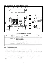
Страница 21: ...is installed on a place such as the engine main body where the vibration acceleration exceeds 1G use the specified rubber vibration insulators Fit the rubber vibration insulators in the vertical dire...

Страница 22: ...the wiring between sensors and a controller For one engine limit the total length of the wires within 150 m from the end sensor and the controller Even if two engines are used the total length of the...

Страница 23: ...esel can provide this special cable In the case of ordering please specify necessary length When you need it anything other than normal length please consult with Daihatsu Shape of a connector can be...

Страница 24: ...mmunication lines with a color of cable jacket and connect it without wrong Table Relation between Wire Colors and Corresponding Functions Daihatsu option cable 4 0 5 Wire color Name Signal type Brown...

Страница 25: ...Please do not look for the fit position after putting connectors together The connector pins may be broken and the broken pins may cause imperfect contact 2 Tighten a cable side fixing ring with your...

Страница 26: ...outputs In case of one engine 3 contacts In case of two engines 5 contacts 2 Terminal connection Clamp type terminal block Fig 25 Controller terminal arrangement diagram Fig 26 Schematic drawing of th...

Страница 27: ...r and solenoid valves and for the power supply lines to prevent noise impacts As various sizes of marine use gland packing suitable for the wiring are supplied with the detector use the correct size g...

Страница 28: ...llows 1 For sensor units line Gland size 15c Option cable 4x0 5mm Change the packing to the supplied packing bore diameter 7 mm Cable for ships Installed packing bore diameter 13 mm 2 For power supply...

Страница 29: ...ce for disconnection detection The jumper settings are shown below Set the jumper according to the specified resistance value JP302 ENGINE A HIGH ALARM JP301 ENGINE B HIGH ALARM Jumper between 1 and 2...

Страница 30: ...rs by pinching the locking devices on both ends of the connector and pulling the connector out if they make wiring difficult Connect the shielding wire to a shielded conductor cable connecting termina...

Страница 31: ...t to damage the core conductor Using the cable bared in the wrong length at the end or with the core damaged may cause insulation defect poor contact or wire disconnection 2 Lightly pull the cables on...

Страница 32: ...r unit Set the rotary switch 16 channels in the sensor unit to the specified position 0 to F Please set the node number from 0 sequentially from a No 1 cylinder not to overlap When one engine is conne...

Страница 33: ...concentration in crankcase of a diesel engine varies significantly depending on the difference of the engine type each cylinder and operating conditions Therefore normally the full load setting is pe...

Страница 34: ...correctly set for node and termination 11 2 Steps from the first power ON to practical operation Shown below is the flow diagram for settings to be made from the power ON to the actual operation FULL...

Страница 35: ...engines and defining the selected number by pressing the ENTER key 2 Set the number of sensors to be installed per engine Use the upward and downward arrow keys to select a number and define the selec...

Страница 36: ...y set for the full load 11 3 Full load mist density level setting The full load misty density level must be set in practical operation mode to properly operate the detector Operate the installed engin...

Страница 37: ...3 Set the number of engines number of sensors and items to be excluded from average value computing according to the displayed menu 11 5 Alarm operation check This is the function to check if the MD...

Страница 38: ...et value as required with the upward and downward arrow keys and press the ENTER key to define the final value 4 The currently detected value and set value are displayed Select the 1 CHECK and press t...

Страница 39: ...hecked the change of the mist level on the controller LCD when the engine working and stopped in daily operation check If the mist level of engine working is increased more than that of engine stop th...

Страница 40: ...t density The alarm is given in the early stage when the mist density starts increasing abnormally from the oil mist density during normal operation 2 Confirmation of mist density The controller can i...

Страница 41: ...e sensor unit 2 Check for oil leak from the sensor unit mounting screws If the oil leaks reinstall the sensor unit while referring to Section 8 INSTALLATION 3 Check that the controller main body does...

Страница 42: ...10 to 12 will flash to indicate the system failure status 4 The output relay is held It can be restored by turning off power Turn off the power switch and reconnect the disconnected wire correctly to...

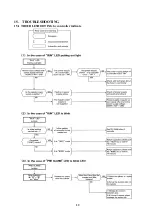
Страница 43: ...40 15 TROUBLESHOOTING 15 1 TROUBLESHOOTING by controller indicate Original content from www daihatsu cc Issued to HORIZON TANKERS LIMITED S A...

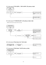
Страница 44: ...41 Original content from www daihatsu cc Issued to HORIZON TANKERS LIMITED S A...

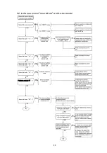
Страница 45: ...42 17 Original content from www daihatsu cc Issued to HORIZON TANKERS LIMITED S A...

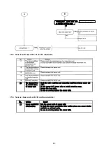
Страница 46: ...rotation range Arrange the loop cable In case no recover replace the sensor unit No Outline Remedy 17 Sensor sensitivity deterioration Wash the sensor part of sensor unit To check the sensor sensitivi...

Страница 47: ...44 15 4TROUBLESHOOTING by sensor unit indicate Original content from www daihatsu cc Issued to HORIZON TANKERS LIMITED S A...

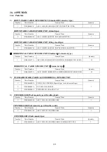
Страница 48: ...L CABLE SENSOR UNIT Connector type Number Parts Number Name of Parts Quantity 2 NN00465035A ASSY MD SX HORIZONTAL WIRING SENSOR CONNECTOR 3 STANDARD SPARE PARTS ACCESSORIES for SENSOR UNIT Number Part...

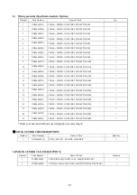
Страница 49: ...1M 2 NN00646002A CABLE MD SX BOTH SIDES CONNECTOR 2M 3 NN00646003A CABLE MD SX BOTH SIDES CONNECTOR 3M 4 NN00646004A CABLE MD SX BOTH SIDES CONNECTOR 4M 5 NN00646005A CABLE MD SX BOTH SIDES CONNECTOR...

Страница 50: ...A CABLE MD SX ONE SIDE CONNECTOR 14M 14 NN00646032A CABLE MD SX ONE SIDE CONNECTOR 15M 15 NN00646033A CABLE MD SX ONE SIDE CONNECTOR 20M 16 NN00646034A CABLE MD SX ONE SIDE CONNECTOR 25M 17 NN00646035...

Страница 51: ...new oil from existing system oil Please replace the system oil periodically in following to the system oil control of engine also you can recover the lowered sensitivity of sensor by applying the was...

Страница 52: ...break down the probe of sensor Prepare for the following article Use rubber glove Container for the sensor cleaning Bottle with more than 250mL of capacity two pieces Yunisol H Transparent Liquid 200m...

Страница 53: ...50 5 This cleaning method will be applied to oil mist sensor on the 2cycle engine with less contamination of lubricant oil Original content from www daihatsu cc Issued to HORIZON TANKERS LIMITED S A...

Страница 54: ...good sensitivity of sensor Check the indication Good LV1 LV2 by connecting optional sensor It confirms it by the following methods when there is no checker Original content from www daihatsu cc Issued...

Страница 55: ...52 1 When there is a difference of the digital value when the organization stops and it drives in one or less Original content from www daihatsu cc Issued to HORIZON TANKERS LIMITED S A...

Страница 56: ...or the disconnection of cable But in short circuit situation of the cable the reliability is same as to use daisy chain wiring d MD SX system can work as normal operation under one disconnection circu...

Страница 57: ...4 All information contained in this Manual is corrected at the time of printing but will be subject to change without notice Original content from www daihatsu cc Issued to HORIZON TANKERS LIMITED S A...

Отзывы: