21
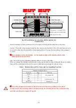
Fig. 22 Specification for connection with the junction box
(Terminal box)
Install 5 terminals in a same junction box for the engine control signal line and above wiring lines.
Caution
)
The shield wiring terminal in junction box connects only the shield of the cable and please do not be
connected to other shield line terminals or the grounding terminal. It causes the missworking of the equipment
by noises
.
※
Please minimize to less than 100mm
for the length of single cable including shield Cable
which exposes from outer skin.
The color of cable jacket of Daihatsu optional cables are shown at this table.
When you connect the Daihatsu optional cable to the general cable for ships, distinguish the power supply
lines and the communication lines with a color of cable jacket, and connect it without wrong.
Table)
Relation between Wire Colors and Corresponding Functions
Daihatsu option cable (4
0.5)
Wire color
Name
Signal type
Brown
+24 V
Power supply line
Blue
0 V
Gray
S+
Communication line
Black
S-
Shield wire
Shielded wire
※
When the equipment is installed, replaced works or during wiring, cabling works, please
execute not only the switching off the controller but also the switching off the outer terminal of the
controller and the power supply all together
JU N C TIO N B O X
←
SENSOR UNIT
RTFRO 4×0.5
CONTROLLER
→
舶用ケーブル
S H IELD W IR E
S H IELD W IR E
T ER M IN A L
専用ケーブル
線径1~1.5m m
2
(A W G 18~16)
舶用ケーブル(4芯以上の一括シールド線)
Wire diameter: 1 -1.5 mm (AWG18-16)
Specified cable for ship (batch shielded
cable with 4 or more cores)
Specified cable for ship
Option cable
4
×
0.5
mm
2
LENGTH OF EXPOSURE
SINGLE CABLE
※
LENGTH OF EXPOSURE
SINGLE CABLE
※
Original content from www.daihatsu.cc
Issued to HORIZON TANKERS LIMITED S.A.


