10
6.
DISPLAY AND FUNCTIONS OF SENSOR UNIT
Fig. 7
Sensor unit
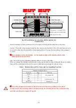
Each sensor unit has three status indicating lamps (LEDs); POWER (green), ALARM (red), and FAILURE
(yellow).
6.1
Description of function
The light emitted from the LED of the sensor unit is diffused and reflected by the oil mist in the sensor hood,
and then received by the photo receiver diode (PD). After amplification and A-D conversion, the output from
the photo receiver is input to the CPU for arithmetic operation, and then transferred to the controller as the oil
mist density data.
6.2
“POWER” LED
This lamp is located on the left of the surface of the sensor unit case. When the green LED is on, this means that
power is being supplied from the controller and the CPU is working normally.
6.3
“ALARM” LED
The controller detects the alarm status based on the oil mist density detected by the sensor unit.
There are two alarm statuses, “PRE ALARM” and “HIGH ALARM”. Upon occurrence of any alarm, the red
LED in the center of the case surface flashes (PRE ALARM) or lights (HIGH ALARM) according to the signal
from the controller.
6.4
“FAILURE” LED
The sensor unit has a self-diagnosis function. If any trouble is found, the yellow LED on the right of the case
surface will turn on.
Upon occurrence of a light receiving or emitting element output trouble, a CPU trouble, a thermistor trouble or a
circuit trouble, the LED lights.
In addition, when the controller is set in the test mode, the LED of all sensor units becomes blinking.
“FAILURE”
DISPLAY
“ALARM”
DISPLAY
“
P
OWER”DISPLAY
Connector ground
Slide cover
Fixed Screw of slide cover
“FAILURE”
DISPLAY
“ALARM”
DISPLAY
“
P
OWER”DISPLAY
Connector ground
Slide cover
Screw of
cover
Original content from www.daihatsu.cc
Issued to HORIZON TANKERS LIMITED S.A.


