Dahua NVR21-4KS3 Series Скачать руководство пользователя страница 451

User's Manual 

431 

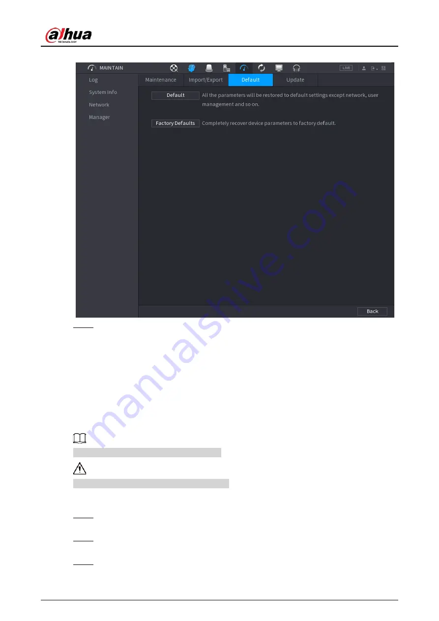
Figure 5-323 Default 


Step 2 

Restore the settings. 


Default

: Restore all the configurations except network settings and user management 

to the default. 


Factory Default

: Restore all the configurations to the factory default settings. 

5.19.4.3.2 Resetting Device through the Reset Button   

Background Information 

You can use the reset button on the mainboard to reset the Device to the factory default settings. 


The reset button is available on select models. 


After resetting, all the configurations will be lost. 

Procedure 

Step 1 

Disconnect the Device from power source, and then remove the cover panel. For details 
about removing the cover panel, see "3.3 HDD Installation". 

Step 2 

Find the reset button on the mainboard, and then connect the Device to the power source 
again. 

Step 3 

Press and hold the reset button for 5 seconds to 10 seconds. 

Содержание NVR21-4KS3 Series

Страница 1: ...Network Video Recorder User s Manual ZHEJIANG DAHUA VISION TECHNOLOGY CO LTD V2 3 5...

Страница 2: ...death or serious injury Indicates a medium or low potential hazard which if not avoided could result in slight or moderate injury Indicates a potential risk which if not avoided could result in prope...

Страница 3: ...SSA and Quick Pick June 2022 V2 1 0 Updated cluster service April 2022 V2 0 0 Added intelligent diagnosis Added report query Added resetting password through DMSS app Added LLDP Updated several figur...

Страница 4: ...h include but are not limited Providing clear and visible identification to inform people of the existence of the surveillance area and provide required contact information About the Manual The manual...

Страница 5: ...Manual IV Please visit our website contact the supplier or customer service if there is any problem occurred when using the device If there is any uncertainty or controversy please see our final expla...

Страница 6: ...ation Operate the Device within the rated range of power input and output Do not disassemble the Device Use the Device under allowed humidity and temperature conditions Installation Requirements Do no...

Страница 7: ...pply of the Device is connected to a power socket with protective earthing Use power cords that conform to your local requirements and are rated specifications Before connecting the power supply make...

Страница 8: ...6P 4KS2 NVR48 4KS2 NVR48 16P 4KS2 NVR48 4KS2 L NVR48 16P 4KS2 L NVR22 4KS2 NVR22 P 4KS2 NVR22 8P 4KS2 NVR22 4KS3 NVR22 P 4KS3 NVR22 8P 4KS3 NVR22 16P 4KS3 NVR52 8P 4KS2E NVR52 16P 4KS2E NVR54 16P 4KS2...

Страница 9: ...KS2 L NVR41 8P 4KS2 L NVR21 S3 NVR21 P S3 NVR21 8P S3 Series 32 2 2 7 NVR42 4KS2 NVR42 P 4KS2 NVR42 8P 4KS2 NVR42 16P 4KS2 NVR42 4KS2 L NVR42 P 4KS2 L NVR42 8P 4KS2 L NVR42 16P 4KS2 L NVR42 EI NVR42 P...

Страница 10: ...VR21HS P 4KS2 NVR21HS 8P 4KS2 NVR21HS W 4KS2 NVR11HS S3H NVR11HS P S3H NVR11HS 8P S3H NVR21HS I NVR21HS I2 NVR21HS P I NVR21HS P I2 NVR21HS 8P I NVR21HS 8P I2 NVR21HS S3 NVR21HS P S3 NVR21HS 8P S3 NVR...

Страница 11: ...Series 106 3 5 6 NVR42 4KS2 NVR42 P 4KS2 NVR42 8P 4KS2 NVR42 16P 4KS2 NVR42 4KS2 L NVR42 P 4KS2 L NVR42 8P 4KS2 L NVR42 16P 4KS2 L NVR42 EI NVR42 P EI NVR42 8P EI NVR42 16P EI 106 3 5 7 NVR54 4KS2 NVR...

Страница 12: ...50 5 6 7 3 2 Configuring Tours 151 5 6 7 3 3 Configuring Patterns 152 5 6 7 3 4 Configuring AutoScan 152 5 6 7 4 Using PTZ Functions 153 5 6 7 4 1 Presets 153 5 6 7 4 2 Tours 153 5 6 7 4 3 Patterns 15...

Страница 13: ...182 5 7 6 1 Configuring Audio and Video Encoding Settings 182 5 7 6 2 Snapshot 185 5 7 7 Modifying Channel Name 186 5 7 8 Checking the PoE Status 187 5 7 9 Updating Remote Devices 188 5 7 10 Viewing...

Страница 14: ...on 227 5 9 6 Face Recognition 227 5 9 6 1 Enabling Smart Plan 228 5 9 6 2 Creating Face Database 228 5 9 6 2 1 Creating Local Face Databases 228 5 9 6 2 2 Creating Remote Face Databases 229 5 9 6 2 3...

Страница 15: ...tay Detection 269 5 9 8 3 AI Search Stereo Analysis 270 5 9 9 Video Metadata 271 5 9 9 1 Enabling Smart Plan 271 5 9 9 2 Configuring Video Metadata 272 5 9 9 3 AI Search Video Metadata 273 5 9 9 3 1 H...

Страница 16: ...15 3 Report Query 298 5 9 16 Main sub Tracking 299 5 9 17 Video Quality Analytics 301 5 9 17 1 Configuring Video Quality Analytics 301 5 9 17 2 Analytics List 303 5 9 18 Entries Frequency 303 5 9 19 S...

Страница 17: ...i AP 334 5 11 5 1 General Settings 334 5 11 5 2 Advanced Settings 335 5 11 6 3G 4G 337 5 11 7 Cellular Network 338 5 11 8 Repeater 340 5 11 9 PPPoE 343 5 11 10 DDNS 343 5 11 11 UPnP 345 5 11 11 1 Conf...

Страница 18: ...2 1 Adding User 375 5 13 2 2 Changing Password 377 5 13 3 Resetting Password 378 5 13 3 1 Enabling Password Reset 378 5 13 3 2 Resetting Password on Local Page 378 5 13 4 ONVIF User 383 5 14 Security...

Страница 19: ...17 1 2 Connection Mode 414 5 17 2 Search 414 5 18 Audio 415 5 18 1 File Management 415 5 18 2 Audio Play 417 5 18 3 Broadcast 418 5 19 Operation and Maintenance 420 5 19 1 Log 420 5 19 2 System 421 5...

Страница 20: ...eration 438 6 1 Network Connection 438 6 2 Web Login 438 6 3 Web Main Menu 439 6 4 Cluster Service 441 6 4 1 Configuring Cluster IP 441 6 4 2 Main Device 442 6 4 3 Sub Device 443 6 4 4 Transferring Vi...

Страница 21: ...transportation and education 1 2 Features AI Functions AI functions are available on select models and vary with models Face detection The system can detect the faces are on the video image Face reco...

Страница 22: ...urred time Support specified zone enlargement User Management Users can be added to user groups for management Each group has a set of permissions that can be individually edited Storage With correspo...

Страница 23: ...SB record backup You can back up the record files in devices such as network storage server peripheral USB 2 0 device and burner Network Management Supervise NVR configuration and control power via Et...

Страница 24: ...2 NVR21 P 4KS2 NVR21 8P 4KS2 NVR21 S3 NVR21 P S3 NVR21 8P S3 NVR21 4KS3 NVR21 P 4KS3 NVR21 8P 4KS3 NVR41 EI NVR41 P EI NVR41 8P EI NVR41 4KS3 NVR41 P 4KS3 NVR41 8P 4KS3 Series The figure is for refere...

Страница 25: ...indicator light The red light becomes on when the power connection is normal 3 Network status indicator light The red light becomes on when the network connection is abnormal 2 1 2 NVR11HS S3H NVR11HS...

Страница 26: ...ral USB storage device mouse and more 2 1 3 NVR52 4KS2 NVR52 8P 4KS2 NVR52 16P 4KS2 NVR42 4KS2 NVR42 P 4KS2 NVR42 8P 4KS2 NVR42 16P 4KS2 NVR42 4KS2 L NVR42 P 4KS2 L NVR42 8P 4KS2 L NVR42 16P 4KS2 L NV...

Страница 27: ...R44 16P 4KS2 L NVR54 24P 4KS2 NVR54 16P 4KS2E NVR44 4KS3 series front panel is shown as below Figure 2 5 Front panel The NVR58 4KS2 NVR58 16P 4KS2 NVR48 4KS2 NVR48 16P 4KS2 NVR48 4KS2 L NVR48 16P 4KS2...

Страница 28: ...ion HDD HDD status indicator light The blue light is on when the HDD malfunctions NET Network status indicator light The blue light is on when the network connection is abnormal PWR Power status indic...

Страница 29: ...atus indicator light The blue light is on when the network connection is abnormal POWER Power status indicator light The blue light is on when the power connection is normal USB 2 0 port Connect to pe...

Страница 30: ...el is shown as below Figure 2 11 Front panel 2 1 7 NVR21HS I NVR21HS I2 NVR21HS P I NVR21HS P I2 NVR21HS 8P I NVR21HS 8P I2 NVR44 4KS2 I NVR44 16P 4KS2 I Series The figure is for reference only The NV...

Страница 31: ...ces such as keyboard mouse and USB storage device IR indicator Receives signals from the remote control 2 1 8 NVR22 I NVR22 I2 NVR22 P I NVR22 P I2 NVR22 8P I NVR22 8P I2 NVR22 16P I NVR22 16P I2 NVR5...

Страница 32: ...NVR41HS EI NVR42 EI NVR41HS P EI NVR42 P EI NVR41HS 8P EI NVR42 8P EI NVR42 16P EI NVR44 EI NVR44 16P EI front panel is shown as below Figure 2 17 Front panel The NVR52 XI NVR52 8P XI NVR52 16P XI fro...

Страница 33: ...e IR indicator Receives signals from the remote control 2 1 9 NVR48 I NVR58 I NVR58 I L Series The section takes NVR4832 I NVR5864 I NVR5864 I L NVR5832 I NVR5832 I L series as examples The figure is...

Страница 34: ...s signals from the remote control 2 1 11 NVR48 4KS2 I NVR48 16P 4KS2 I NVR54 EI NVR54 16P EI NVR58 EI NVR58 16P EI NVR48 EI NVR48 16P EI The figures are for reference only The NVR48 4KS2 I NVR48 16P 4...

Страница 35: ...storage device mouse burner and more 2 1 12 NVR608 32 4KS2 Series The following figures are for reference only The NVR608 32 4KS2 front panel is shown as below Figure 2 26 Front panel Table 2 11 Icons...

Страница 36: ...XI NVR608RH 64 XI NVR608RH 128 XI front panel is shown as below Figure 2 27 Front panel Table 2 12 Front panel description Icon Name ALARM Alarm indicator light HDD HDD status indicator light NET Netw...

Страница 37: ...es on after system booted up properly In the system HDD there are device important configuration file factory default configuration file and device initial boot up data 3 Alarm indicator light The ala...

Страница 38: ...on The indicator light becomes on when there is a local alarm 4 Network indicator light The blue network indicator light is on after you connected the device to the network 5 USB port 6 16 HDD slot Af...

Страница 39: ...erence only The front panel of NVR624 XI series is shown as follows Figure 2 31 Front panel Table 2 15 Icons No Name Function 1 Front panel lock 2 USB port 3 Network indicator light The blue network i...

Страница 40: ...ranges from 1 4 5 8 9 12 13 16 17 20 21 24 You can see there are two indicator lights on the HDD bracket The power indicator light is at the top The light is yellow after you connected the device to t...

Страница 41: ...3 NVR41 8P 4KS3 Series The NVR21 4KS2 NVR21 4KS3 NVR41 EI NVR41 4KS3 is shown as below Figure 2 33 Rear panel The NVR41 P EI NVR21 P 4KS2 NVR21 P 4KS3 NVR41 P 4KS3 is shown as below Figure 2 34 Rear p...

Страница 42: ...0 Mbps or 10 100 1000 Mbps NVR41 P EI NVR41 P 4KS3 series supports 10 100 Mbps NVR41 8P EI NVR41 8P 4KS3 series supports 10 100 1000 Mbps The parameters might be different according to the models Plea...

Страница 43: ...NVR41HS 8P 4KS2 NVR41HS 4KS2 L NVR41HS P 4KS2 L NVR41HS 8P 4KS2 L NVR21HS S3 NVR21HS P S3 NVR21HS 8P S3 NVR21HS 4KS3 NVR21HS P 4KS3 NVR21HS 8P 4KS3 NVR41HS EI NVR41HS P EI NVR41HS 8P EI NVR41HS 4KS3...

Страница 44: ...work port 10 100 1000 Mbps self adaptive Ethernet port Connect to the network cable NVR41HS EI NVR41HS 4KS3 series supports 10 100 Mbps or 10 100 1000 Mbps NVR41HS P EI NVR41HS P 4KS3 series supports...

Страница 45: ...t on 1 window video playback GND Ground end PoE PORTS PoE port Built in switch Support PoE function For PoE series product you can use this port to provide power to the network camera 2 2 3 NVR22 4KS2...

Страница 46: ...input 53 VDC 1 81 A For NVR22 8P 4KS3 input 54 VDC 2 22 A Network port 10 100 Mbps self adaptive Ethernet port Connect to the network cable USB port USB port Connect to mouse USB storage device and m...

Страница 47: ...ct you can use this port to provide power to the network camera 2 2 4 NVR52 4KS2 NVR52 8P 4KS2 NVR52 16P 4KS2 NVR52 24P 4KS2 NVR52 8P 4KS2E NVR52 16P 4KS2E NVR52 EI NVR52 8P EI NVR52 16P EI NVR42 16P...

Страница 48: ...52 EI series rear panel is shown as below Figure 2 51 Rear panel The NVR52 8P EI series rear panel is shown as below Figure 2 52 Rear panel The NVR52 16P EI series rear panel is shown as below Figure...

Страница 49: ...og audio signal output from the devices such as microphone pickup MIC OUT Audio output port Audio output port It is to output the analog audio signal to the devices such as the sound box Bidirectional...

Страница 50: ...re the ePoE ports ePoE port supports 300 meters 100 Mbps 800 meters 10 Mbps Port 9 to port 16 are general PoE ports The 8 PoE series product supports total 130 W The 16 PoE series product supports tot...

Страница 51: ...USB port USB port Connect to mouse USB storage device USB burner and more HDMI High Definition Media Page High definition audio and video signal output port It transmits uncompressed high definition...

Страница 52: ...ontrol devices such as speed dome PTZ B RS485_B It is the cable B You can connect to the control devices such as speed dome PTZ CTRL CTRL 12 V Controller 12 V power output It is to control the on off...

Страница 53: ...8P 4KS2 NVR41 8P 4KS2 L series rear panel is shown as below Figure 2 64 Table 2 21 Ports Port Name Connection Function USB port USB port Connect to mouse USB storage device USB burner and more Network...

Страница 54: ...d box Bidirectional talk output Audio output on 1 window video monitor Audio output on 1 window video playback PoE PORTS PoE port Built in switch Support PoE function For PoE series product you can us...

Страница 55: ...16P 4KS2 NVR42 8P EI NVR42 8P 4KS3 NVR42 16P 4KS3 series product only MIC IN Audio input port Bidirectional talk input port It is to receive the analog audio signal output from the devices such as mic...

Страница 56: ...ure IP address or transfer transparent COM data HDMI High Definition Media Page High definition audio and video signal output port It transmits uncompressed high definition video and multiple channel...

Страница 57: ...gnal to the devices such as the sound box Bidirectional talk output Audio output on 1 window video monitor Audio output on 1 window video playback VIDEO OUT Video output port CVBS output 1 16 Alarm in...

Страница 58: ...device Please note the supplying power shall be below 1 A Network port 10 100 1000 Mbps self adaptive Ethernet port Connect to the network cable eSATA eSATA port External SATA port It can connect to...

Страница 59: ...on off button Power input port 90 264 12 VAC 12 5 A 53 V 2 83 A MIC IN Audio input port Bidirectional talk input port It is to receive the analog audio signal output from the devices such as micropho...

Страница 60: ...control devices such as speed dome PTZ CTRL CTRL 12 V Controller 12 V power output It is to control the on off alarm relay output It can be used to control the device alarm output At the same time it...

Страница 61: ...t Built in Switch Support PoE For PoE series product you can use this port to provide power to the network camera 2 2 10 NVR21 W 4KS2 Series Figure 2 75 Rear panel Table 2 25 Ports Port Name Connectio...

Страница 62: ...ideo output port VGA video output port Output analog video signal It can connect to the monitor to view analog video Power input port Input 12 VDC 2 A WPS RESET Reset WPS function Device Wi Fi reset a...

Страница 63: ...eset WPS function Device Wi Fi reset and WPS function button Hold down this button for 5 seconds and above to restore Wi Fi AP to defaults Press this button for less than 2 seconds and then press the...

Страница 64: ...the network cable Power input port Power socket GND Ground end 2 2 13 NVR22 I NVR22 I2 Series The figures are for reference only Figure 2 78 Rear panel Figure 2 79 Rear panel Table 2 28 Ports Port Na...

Страница 65: ...an use this port to provide power to the network camera 1 4 Alarm input port 1 4 There are two types NO normal open NC normal close When your alarm input device is using external power please make sur...

Страница 66: ...ut from the devices such as microphone pickup MIC OUT Audio output port Audio output port It is to output the analog audio signal to the devices such as the sound box Bidirectional talk output Audio o...

Страница 67: ...port It is to receive the analog audio signal output from the devices such as microphone pickup MIC OUT Audio output port Audio output port It is to output the analog audio signal to the devices such...

Страница 68: ...le channel data to the HDMI port of the display device HDMI version is 1 4 MIC IN Audio input port Bidirectional talk input port It is to receive the analog audio signal output from the devices such a...

Страница 69: ...ure 2 85 Rear panel Figure 2 86 Rear panel Table 2 32 Ports Port Name Connection Function GND Ground end USB port USB port Connect to mouse USB storage device and more HDMI High Definition Media Page...

Страница 70: ...switch Support PoE function For PoE series product you can use this port to provide power to the network camera 1 4 Alarm input port 1 4 There are two types NO normal open NC normal close When your a...

Страница 71: ...t Connect to the network cable USB port USB port Connect to mouse USB storage device and more VGA VGA video output port VGA video output port Output analog video signal It can connect to the monitor t...

Страница 72: ...off button Power input port Power socket 2 2 19 NVR21HS I NVR21HS I2 Series The figure is for reference only Figure 2 88 Rear panel Table 2 34 Rear panel description Port Name Connection Function GND...

Страница 73: ...duct you can use this port to provide power to the network camera Power input port Power socket 2 2 20 NVR21HS P I NVR21HS P I2 Series The figure is for reference only Figure 2 89 Rear panel Table 2 3...

Страница 74: ...I NVR21HS 8P I2 Series The figure is for reference only Figure 2 90 Rear panel Table 2 36 Ports Port Name Connection Function GND Ground end USB port USB port Connect to mouse USB storage device and m...

Страница 75: ...e only Figure 2 91 Rear panel Table 2 37 Ports No Port Name Function 1 Power input port Input power of 100 240 V and 50 60 Hz 2 Power button Turns on off the NVR 3 PoE port Built in switch It can prov...

Страница 76: ...m input includes two types NO normal open and NC normal close When your alarm input device is using external power make sure the device and the NVR have the same GND GND Alarm input ground port NO C O...

Страница 77: ...ls the alarm device with the presence or absence of voltage It can also be used as power input for some alarm devices such as alarm detectors The two ports serve as another group of alarm output ports...

Страница 78: ...jump the HDD when there is peripherally connected HDD 3 VGA port VGA video output port Output analog video signal It can connect to the monitor to view analog video 4 RS 232 port It is for general COM...

Страница 79: ...ame time it can also be used as the power input source of some devices such as alarm detector The two ports serve as anoth er group of alarm output ports 12 V power output port It can provide power to...

Страница 80: ...6P I L series as examples The figure is for reference only Figure 2 95 Rear panel Figure 2 96 Rear panel No Port Name Function 1 Power button Turns on off the NVR 2 PoE port Built in switch It can pro...

Страница 81: ...ce is using external power make sure the device and the NVR have the same GND Alarm output port NO1 NO5 C1 C5 NC5 Five groups of alarm output ports Group 1 NO1 C1 Group 2 NO2 C2 Group 3 NO3 C3 Group 4...

Страница 82: ...output port It is to output analog audio signal to devices such as sound box Bidirectional talk output Audio output on 1 window video monitor Audio output on 1 window video playback 9 USB port USB 3 0...

Страница 83: ...itch It can provide power for IPC 16 PoE ports 1 8 are ePoE ports support 300m 100M 800m 10M 9 16 are regular PoE ports The device supports 150 W total power 8 PoE ports 1 8 are ePoE ports support 300...

Страница 84: ...utput of NVR4216 16P I Alarm input port 1 4 They receive signals from external alarm source Alarm input includes two types NO normal open and NC normal close When your alarm input device is using exte...

Страница 85: ...7 Network port 10 100 1000 Mbps self adaptive Ethernet port Connect to the network cable 8 MIC IN Bidirectional talk input port It is to receive analog audio signal from devices such as microphone sou...

Страница 86: ...4KS2 NVR608 128 4KS2 NVR608H 32 XI NVR608H 64 XI NVR608H 128 XI series rear panel is shown as below Figure 2 101 Rear panel 2 Figure 2 102 Rear panel 3 The NVR608RH 32 XI NVR608RH 64 XI NVR608RH 128 X...

Страница 87: ...put 6 VGA port 7 Network port 8 HDMI port 9 NVR608 4K USB 2 0 port NVR608 4KS2 USB 3 0 port 10 USB 3 0 port 11 eSATA port 12 Ground 2 2 28 NVR616 4KS2 NVR616 XI Series The general series rear panel of...

Страница 88: ...t 10 USB 3 0 port 11 USB 3 0 port 12 eSATA port 13 SAS extension port 14 Alarm input output RS 485 port 15 HDMI port High definition decoding card is not installed in standard hardware configuration y...

Страница 89: ...rt 6 HDMI Port High definition decoding card is not installed in standard hardware configuration you can purchase as needed 7 VGA Port 8 AUDIO IN RCA Connector 9 AUDIO OUT RCA Connector 10 Alarm In Ou...

Страница 90: ...ame 1 Power Input 2 Alarm In Out 3 Network Port 4 USB Port 5 eSATA Port 6 HDMI Port High definition decoding card is not installed in standard hardware configuration you can purchase as needed 7 VGA P...

Страница 91: ...tion Media Page High definition audio and video signal output port It transmits uncompressed high definition video and multiple channel data to the HDMI port of the display device HDMI version is 1 4...

Страница 92: ...onitor Audio output on 1 window video playback GND Ground end 2 2 31 NVR54 EI NVR54 16P EI NVR58 EI NVR58 16P EI NVR54 XI NVR 58 XI Series The NVR54 EI series rear panel is shown as below Figure 2 110...

Страница 93: ...able eSATA eSATA port External SATA port It can connect to the device of the SATA port Please jump the HDD when there is peripheral connected HDD USB 3 0 USB port USB port Connect to mouse USB storage...

Страница 94: ...oup 4 port NO4 C4 Group 5 port NO5 C5 NC5 Output alarm signal to the alarm device Please make sure there is power to the external alarm device NO Normal open alarm output port C Alarm output public en...

Страница 95: ...PoE ports ePoE port supports 300 meters 100Mbps 800 meters 10Mbps Port 9 to port 16 are general PoE ports The 16 PoE series supports total 150W 2 2 32 NVR50 EI Series The NVR50 EI series rear panel is...

Страница 96: ...sable power output when alarm is canceled Current is 500 mA P 12 V Rated current output Current is 500 mA GND A B 485 communication port They are used to control devices such as PTZ Please parallel co...

Страница 97: ...User s Manual 77 Figure 2 118 Alarm input port 1...

Страница 98: ...the alarm input port ALARM of the NVR When there is peripheral power supplying for the alarm device please make sure it is earthed with the NVR 2 3 3 Alarm Output Port There is peripheral power suppl...

Страница 99: ...C 1 minute Between touch and winding 1000 VAC 1 minute Surge voltage Between touches with same polarity 1500 V 10 160 s Length of open time 3 ms max Length of close time 3 ms max Longevity Mechanical...

Страница 100: ...Connect the speaker or the pickup to the audio output port in the PC 2 Connect the earphone or the sound box to the first audio input port in the device rear panel 3 Log in to the web and then enable...

Страница 101: ...e Installation All the installation and operations here should conform to your local electric safety rules 3 1 Device Installation Diagram Please see the following diagram to install the NVR Figure 3...

Страница 102: ...need to provide the serial number on the label when calling the after sales service 3 3 HDD Installation For the first time installation make sure whether the HDD has been installed or not We recomme...

Страница 103: ...NVR if it is not convenient to connect the HDD data cable and power cable at first Procedure Step 1 Loosen the screws of the bottom of the chassis Figure 3 2 Lossen screws Step 2 Place the HDD in acc...

Страница 104: ...4 Secure screws Step 4 Connect the HDD cable and power cable to the HDD and the mainboard respectively Figure 3 5 Connect cables Step 5 Put the cover back and then fix the screws of the rear panel The...

Страница 105: ...R21HS 4KS2 NVR21HS P 4KS2 NVR21HS 8P 4KS2 NVR21HS W 4KS2 NVR11HS S3H NVR11HS P S3H NVR11HS 8P S3H NVR21HS I NVR21HS I2 NVR21HS P I NVR21HS P I2 NVR21HS 8P I NVR21HS 8P I2 NVR21HS S3 NVR21HS P S3 NVR21...

Страница 106: ...irection of the arrow as shown in the figure below Figure 3 8 Remove cover Step 3 Turn over the device and align the HDD to the four holes of bottom panel and then fix the HDD with screws Figure 3 9 A...

Страница 107: ...8P 4KS2 L NVR42 16P 4KS2 L NVR52 4KS2 NVR52 8P 4KS2 NVR52 16P 4KS2 NVR52 24P 4KS2 NVR22 4KS2 NVR22 P 4KS2 NVR22 8P 4KS2 NVR52 8P 4KS2E NVR22 I NVR22 I2 NVR22 P I NVR22 P I2 NVR22 8P I NVR22 8P I2 NVR2...

Страница 108: ...s Manual 88 Figure 3 12 Remove screws Step 2 Remove the case cover along the direction shown in the following arrow Figure 3 13 Remove cover Step 3 Match the four holes on the baseboard to place the...

Страница 109: ...ign HDD Step 4 Turn the device upside down match the screws with the holes on the HDD and then fasten them The HDD is fixed to the baseboard Figure 3 15 Fasten screws Step 5 Connect the HDD data cable...

Страница 110: ...les Step 6 Put back the cover and fasten the four screws on the rear panel to complete the installation Figure 3 17 Put back cover 3 3 4 NVR54 4KS2 NVR54 16P 4KS2 NVR44 4KS2 NVR44 16P 4KS2 NVR44 4KS2...

Страница 111: ...have different number of HDDs Procedure Step 1 Remove the fixing screws on the rear panel of the device Figure 3 18 Remove screws Step 2 Remove the case cover along the direction shown in the followi...

Страница 112: ...s 1 5U Figure 3 21 Remove screws 2U Step 4 Match the four screw holes on the HDD with the four holes on the bracket and then fasten the screws The HDD is fixed to the bracket Figure 3 22 Fasten screws...

Страница 113: ...HDD brackets This step is required for 2U devices only Figure 3 24 Lock brackets Step 7 Place the bracket to the device and then fasten the screws on the sides of the bracket Figure 3 25 Fasten screw...

Страница 114: ...onnect cables Step 9 Put back the cover and fasten the screws on the rear panel to complete the installation Figure 3 27 Fasten screws 3 3 5 NVR608 64 4KS2 NVR608 128 4KS2 NVR608H 32 XI NVR608H 64 XI...

Страница 115: ...2 Press the button on the 2 sides to open the front panel Figure 3 29 Open front panel Step 3 Match the 4 screw holes on the HDD with the 4 holes on the bracket and then fasten the screws Figure 3 30...

Страница 116: ...panel and then tighten the lock on the front panel Figure 3 32 Lock front panel 3 3 6 NVR616 4KS2 Series Background Information The following figures are for reference only Procedure Step 1 Press the...

Страница 117: ...o the HDD box along the direction shown in the following arrow Figure 3 34 Put HDD into box Step 3 Fasten the screws on the sides of the HDD box Figure 3 35 Fasten screws Step 4 Insert the HDD box int...

Страница 118: ...e to avoid any damage to the HDD slot Figure 3 36 Close the handle 3 4 CD ROM Installation Procedure Step 1 Open the top cover and then remove the HDD bracket Figure 3 37 Open the top cover Step 2 Tak...

Страница 119: ...at the HDD bracket Figure 3 40 Fix bracket Step 4 Install a pair of the CD ROM bracket Please make sure that the reverse side is secure too Figure 3 41 Install bracket Figure 3 42 Install bracket rev...

Страница 120: ...A burner Step 6 Use screw driver to fix the screws Figure 3 44 Fasten screws Step 7 Put the bracket back Please adjust the CD ROM to the proper position so that the button of the front panel is direct...

Страница 121: ...User s Manual 101 Figure 3 45 Put bracket back Step 8 Connect the SATA cable and power wire Figure 3 46 Connect cables Step 9 Secure the HDD bracket and put the top cover back...

Страница 122: ...ures are for reference only and might differ from the actual product 3 5 1 NVR41 4KS2 NVR41 P 4KS2 NVR41 8P 4KS2 NVR41 4KS2 L NVR41 P 4KS2 L NVR41 8P 4KS2 L NVR21 4KS2 NVR21 P 4KS2 NVR21 8P 4KS2 NVR21...

Страница 123: ...User s Manual 103 S3 NVR41 EI NVR41 P EI NVR41 8P EI Figure 3 48 Typical connection...

Страница 124: ...1HS S3H NVR11HS P S3H NVR11HS 8P S3H NVR41HS 4KS2 NVR41HS P 4KS2 NVR41HS 8P 4KS2 NVR41HS 4KS2 L NVR41HS P 4KS2 L NVR41HS 8P 4KS2 L NVR21HS 4KS2 NVR21HS P 4KS2 NVR21HS 8P 4KS2 NVR21HS I NVR21HS I2 NVR2...

Страница 125: ...R41HS P EI NVR41HS 8P EI Figure 3 50 Typical connection 3 5 4 NVR22 4KS2 NVR22 P 4KS2 NVR22 8P 4KS2 NVR22 I NVR22 I2 NVR22 P I NVR22 P I2 NVR22 8P I NVR22 8P I2 NVR22 16P I NVR22 16P I2 Series Figure...

Страница 126: ...2 4KS2 NVR52 8P 4KS2 NVR52 16P 4KS2 NVR52 24P 4KS2 NVR52 8P 4KS2E NVR52 16P 4KS2E Series Figure 3 52 Typical connection 3 5 6 NVR42 4KS2 NVR42 P 4KS2 NVR42 8P 4KS2 NVR42 16P 4KS2 NVR42 4KS2 L NVR42 P...

Страница 127: ...S2 L NVR42 EI NVR42 P EI NVR42 8P EI NVR42 16P EI Figure 3 53 Typical connection 3 5 7 NVR54 4KS2 NVR54 16P 4KS2 NVR58 4KS2 NVR58 16P 4KS2 NVR54 24P 4KS2 NVR54 16P 4KS2E NVR58 16P 4KS2E Series Figure...

Страница 128: ...6P 4KS2 NVR44 4KS2 L NVR44 16P 4KS2 L NVR44 4KS2 I NVR44 16P 4KS2 I NVR44 EI NVR44 16P EI Series Figure 3 55 Typical connection 3 5 9 NVR48 4KS2 NVR48 16P 4KS2 NVR48 4KS2 L NVR48 16P 4KS2 L NVR48 4KS2...

Страница 129: ...User s Manual 109 Series Figure 3 56 Typical connection...

Страница 130: ...r s Manual 110 3 5 10 NVR58 I NVR58 I L NVR48 I Series Figure 3 57 Typical connection 3 5 11 NVR54 I NVR54 I L NVR44 I Figure 3 58 Typical connection 3 5 12 NVR52 16P I NVR52 16P I L NVR52 8P I NVR52...

Страница 131: ...User s Manual 111 I L NVR42 8P I NVR42 16P I Series Figure 3 59 Typical connection 3 5 13 NVR4216 I Series Figure 3 60 Typical connection...

Страница 132: ...5 14 NVR608 4KS2 NVR608H XI NVR608RH XI Series The following figure is for reference only and might differ from the actual product Figure 3 61 Typical connection 3 5 15 NVR616 4KS2 Series Figure 3 62...

Страница 133: ...the stable current if necessary UPS is a best alternative measure Procedure Step 1 Connect the device to the monitor and then connect a mouse Step 2 Connect power cable Step 3 Press the power button o...

Страница 134: ...safety keep your login password well and change the password regularly The IP address of the Device is 192 168 1 108 by default Procedure Step 1 Start the NVR Step 2 Set region time zone and time acco...

Страница 135: ...unlock pattern click Skip Once you have configured the unlock pattern the system will require the unlock pattern as the default login method If you did not configure the unlock pattern you need to ent...

Страница 136: ...questions and answers If you forgot the password you can reset the password after entering the answers to the questions Step 6 Click Save 5 2 Startup Wizard Background Information After initializatio...

Страница 137: ...ick Next The number of network adapters might vary with models Configure the IP address of the network adapter according to the actual connection situation 1 Click Figure 5 5 Edit network adapter 2 Co...

Страница 138: ...normally When testing the network status the network is regarded as offline only when both of the two network adapters are disconnected The two network adapters are used under the same LAN The Device...

Страница 139: ...vice to the app Before using the P2P function make sure that the NVR has connected to the WAN The Status becomes Online after you successfully configure P2P Figure 5 6 P2P Step 4 Add cameras according...

Страница 140: ...tab You can remove devices added through plug and play and they can be automatically added again after plug and play is enabled 2 Optional Enable Plug and Play When Plug and Play is enabled the Device...

Страница 141: ...t click OK The configurations through startup wizard take effect after the Device restarts 5 3 Login Log in to the Device to perform local operations Procedure Step 1 Right click the live page and the...

Страница 142: ...User s Manual 122 Figure 5 9 Unlock pattern login...

Страница 143: ...User s Manual 123 Figure 5 10 Password login Step 2 Draw unlock pattern or enter password and then click OK 5 4 Main Menu After login right click the live page and then click Main Menu...

Страница 144: ...the current username 4 Log out of restart or shut down the Device 5 Click the icon to get the QR codes of mobile client and device SN You can add the Device to the mobile client for remote management...

Страница 145: ...nction Titles Click ALARM to go to the ALARM page Figure 5 12 Quick operation bar 1 Table 5 5 Quick operation bar description 1 Icon Description Go to the SEARCH page Go to the ALARM page Go to the AI...

Страница 146: ...to the ACCOUNT page 5 6 Live View After you logged in the system goes to multiple channel live view mode by default You can view the live video of each channel The number of window splits might vary...

Страница 147: ...gation bar might vary with models Procedure Step 1 After login right click the live page and then select Main Menu Step 2 Select System General Basic Step 3 Click to enable navigation bar Step 4 On th...

Страница 148: ...details see 5 10 2 Alarm Status Open the Channel Info page to display the information of each channel Open the Add Camera page Open the NETWORK page For details see 5 19 3 Network Open the Disk Manag...

Страница 149: ...ontrol bar description No Name No Name 1 Instant playback 5 Two way talk 2 Digital zoom 6 Stream switch 3 Instant backup 7 Picture search 4 Manual snapshot 8 Quick pick AcuPick 5 6 3 1 Instant Playbac...

Страница 150: ...two ways Click The icon switches to Select an area The area is enlarged after you release the mouse button For some models when the image is enlarged in this way the selected area is zoomed proportio...

Страница 151: ...stream type of the main stream and sub stream according to current network bandwidth M Main stream Its bit streams are big and definition is high It occupies large network bandwidth suitable for vide...

Страница 152: ...ange Step 3 Select the target face that you want to search for You can select maximum 8 target faces Step 4 Click Search The search results are displayed Figure 5 19 Picture search results Related Ope...

Страница 153: ...video or picture Select the picture and then click Backup You can set save path backup type and file type and then export to the external storage device 5 6 3 8 Quick Pick When connected with select I...

Страница 154: ...hange the search conditions and then click Search You can only select up to 8 targets for search Figure 5 22 Search conditions Step 5 Hover over a search result to view the basic information including...

Страница 155: ...tep 2 Point to the top center of the video of current channel and then the live view control bar appears Figure 5 23 Live view control bar Step 3 When you want to search the target in the image click...

Страница 156: ...User s Manual 136 Figure 5 24 AcuPick human detection...

Страница 157: ...User s Manual 137 Figure 5 25 AcuPick motor vehicle detection Step 5 Configure the search conditions as needed...

Страница 158: ...lter Select from All Favorite Items and Hidden Items When you select the target items the device will only search in this item 4 Similarity Configure the search similarity according to the actual cond...

Страница 159: ...lay on this page Click you can enable the AcuPick function again freeze the image and search for the new target 5 6 4 Shortcut Menu Right click the live view page to bring up the shortcut menu You can...

Страница 160: ...User s Manual 140 The shortcut menu is different for different models Figure 5 28 Shortcut menu 1...

Страница 161: ...tcut menu 2 Figure 5 30 Shortcut menu 3 Table 5 11 Shortcut menu description Function Description Main Menu Go to main menu Search Search and play back videos or images PTZ Control Open the PTZ contro...

Страница 162: ...able or disable crowd distribution function Auto Focus Click to realize auto focus function Make sure the connected camera supports this function Image Click to modify the camera image parameters For...

Страница 163: ...on the right to play the corresponding video Step 3 Click and then select the face attributes that you want to display You can select up to 4 attributes Figure 5 32 Face vehicle properties Step 4 Opti...

Страница 164: ...on the target Step 6 On the search results page double click one search result and then the corresponding recording before and after the event being reported will be automatically played on the right...

Страница 165: ...most 5 6 6 Split Tracking You can track window split for a certain channel Background Information This function is for select models only Procedure Step 1 Right click the live page and then select Spl...

Страница 166: ...color to adjust the videos displayed on split screens You can scroll the mouse in split screens to zoom in or out the video Figure 5 37 Split display 5 6 7 PTZ PTZ is a mechanical platform that carrie...

Страница 167: ...parameters for local type and remote type Before you use local PTZ make sure you have set PTZ protocol otherwise you cannot control the local PTZ Local The PTZ device connects to the NVR through the c...

Страница 168: ...LCOD Address Enter the address for PTZ camera The default is 1 The entered address must be the same with the address configured on the PTZ camera otherwise the system cannot control PTZ camera Baud ra...

Страница 169: ...Image brighter PTZ movement Supports eight directions Fast positioning button Positioning Click the icon and the click any point on the live page The PTZ will turn to this point and locate this point...

Страница 170: ...ot supported by the system Right click once to return to the page of PTZ basic control panel Table 5 14 PTZ functions Icon Function Icon Function Preset Pan Tour Flip Pattern Reset Scan Click the AUX...

Страница 171: ...resent the required position Step 4 Click Setting to complete the preset settings 5 6 7 3 2 Configuring Tours Procedure Step 1 On the expanded PTZ control panel click Step 2 Click the Tour tab Figure...

Страница 172: ...On the expanded PTZ control panel click Step 2 Click the Pattern tab Figure 5 44 Pattern Step 3 In the Pattern box enter the value for pattern Step 4 Click Start to perform the directions operations...

Страница 173: ...Z control panel Figure 5 46 Expanded PTZ control panel 5 6 7 4 1 Presets Procedure Step 1 On the expanded PTZ control panel in the No box enter the value of the preset Step 2 Click to call the preset...

Страница 174: ...nter the value of the border Step 2 Click The PTZ camera performs scanning according to the configured borders Step 3 Click again to stop auto scanning 5 6 7 4 5 Calling AutoPan Procedure Step 1 On th...

Страница 175: ...ure 5 48 EPTZ linkage Table 5 15 Parameters description Parameter Description Channel Select the linkage channel Display Mode Select the number of tracked channels Full screen 1 1 1 3 and 1 5 modes ar...

Страница 176: ...hen select EPTZ Enable EPTZ and then you can view local EPTZ live videos Figure 5 49 EPTZ live view 5 6 7 5 2 EPTZ Live View Some models can directly turned on the EPTZ linkage function in the live pa...

Страница 177: ...t page and then returns to EPTZ live view mode Figure 5 50 EPTZ live view 5 6 8 Wireless Pairing You can use the wireless pairing to quickly add IPCs to the NVR Make sure that the IPC and NVR are on t...

Страница 178: ...er s Manual 158 Figure 5 51 Wireless pairing 5 6 9 Sequence You can configure the sequence of the channels displayed on the live page Procedure Step 1 Right click the live page and then select Sequenc...

Страница 179: ...panel displays the added camera channel number and channel name means camera is online means camera is offline Figure 5 52 Sequence Step 2 On the Sequence panel drag the channel to the desired window...

Страница 180: ...y After you change the channel sequence click Cancel or right click the live view page the system prompts you whether to save the sequence change Click OK to save current settings Click No to exit wit...

Страница 181: ...eo suitable for human eyes On the live page right click the fisheye channel and then select Fisheye You can set fisheye installation mode and display mode For the non fish eye channel the system promp...

Страница 182: ...scription Ceiling mount Ground mount 360 panorama original view 1 de warp window 1 panorama stretching 2 panorama stretching views 1 360 panorama view 3 de warp windows 1 360 panorama view 4 de warp w...

Страница 183: ...1 window playback mode and corresponding fish eye channel click to play Step 3 Right click and then you can go to the de warp playback page For detailed information see Figure 5 57 5 6 11 Temperature...

Страница 184: ...amera You can add cameras on the live page Procedure Step 1 On the live page point to a channel window There is an icon on the channel window Figure 5 59 Add icon Step 2 Click and then configure the p...

Страница 185: ...red by tripwire or intrusion alarms according to the pre defined rules 5 7 Camera 5 7 1 Initializing Remote Devices Background Information You can change the login password and IP address of a remote...

Страница 186: ...formation for the remote device If you select Using current device password and email info the remote device automatically uses NVR admin account information login password and email You can skip this...

Страница 187: ...gure 5 61 Password 2 Enter the password and then confirm it For your device security we recommend you create a strong password according to the password strength indication and change your password re...

Страница 188: ...ssword resetting If you do not want to enter email information cancel the selection of the checkbox and then click Next or Skip Step 6 Set camera IP address DHCP There is no need to enter IP address s...

Страница 189: ...f the IP address one by one to automatically allocate the IP addresses If an IP conflict occurs when you change static IP address the system will notify you of the issue If you change IP addresses in...

Страница 190: ...2 1 Adding Cameras from Search Background Information Search for the remote devices that are on the same network with the NVR and then add the remote devices from the search results We recommend this...

Страница 191: ...ialize the devices For details see 5 7 1 Initializing Remote Devices To view all remote devices added through plug and play you can click the Not Auto Connected tab You can remove devices added throug...

Страница 192: ...details see 5 7 2 3 Importing Cameras View linked information If the remote device has multiple channels you can click the Camera Linked Info to view linked information of the remote device Delete cam...

Страница 193: ...nect the Imou camera to the Device through the ONVIF protocol otherwise the Imou camera added through private protocols cannot be connected Registration ID Enter the registration ID of the remote devi...

Страница 194: ...P Encryption If the remote device is added through ONVIF protocol select the Encrypt checkbox and then the system will provide encryption protection to the data being transmitted To use this function...

Страница 195: ...se the template cannot be imported Step 4 Click Import select the template file and then open it The remote devices in the template are added to the NVR If the remote device in the template has been a...

Страница 196: ...Step 4 Enter username and password of the remote device and then configure the IP address DHCP The remote device gets a dynamic IP address automatically Static You need to enter static IP address subn...

Страница 197: ...on Brightness Adjust the image brightness The bigger the value is the brighter the image will become Contrast Adjust the image contrast The bigger the value is the more obvious the contrast between th...

Страница 198: ...age parameters such as exposure and backlight mode will become unavailable Exposure Auto Iris This function is available when the camera is equipped with the auto iris lens After you enable auto iris...

Страница 199: ...LC In the backlight environment the system lowers the brightness of the brightest section reduces the area of the halo and lowers the brightness of the whole video Close Disable the BLC function WB Mo...

Страница 200: ...turing and video recording under the full color mode The white light turns off when the event stops and then the mode switches to IR mode according to the ambient brightness The status of the illumina...

Страница 201: ...play the time tile on the video image in live view and playback 1 Select Time Title 2 Drag the time title to a desired place 3 Click Apply Channel Title Display the channel tile on the video image in...

Страница 202: ...eded A masking block appears on the video image The number of masking blocks that you can add might differ depending on the camera You can add up to 24 masking blocks Click Clear to delete all masking...

Страница 203: ...educe the video bit stream for non important recorded video to maximize the storage space AI Codec Enable the AI codec function This function can reduce the camera code stream network transmission pre...

Страница 204: ...ommended selecting CBR when there might be only small changes in the monitoring environment VBR variable bit rate The bit rate changes with monitoring scenes Select variable stream when there might be...

Страница 205: ...corded video file is composite audio and video stream Compression Select an audio compression format Sampling Frequency Set how many times per second a sound is sampled The bigger the value the more n...

Страница 206: ...ed period Event The snapshot is taken for motion detection video loss local alarms and other events Size The size is determined by the resolution of the main stream or sub stream of the channel Qualit...

Страница 207: ...enter up to 63 English characters for a channel name When the system is in Chinese or English the content in the text input box excluding password input box can be copied and pasted Step 3 Click Apply...

Страница 208: ...ff When enhancement mode is enabled the transmission distance of the PoE port will be extended 5 7 9 Updating Remote Devices You can update the firmware of the connected network camera through online...

Страница 209: ...that has an update available for it and then click Online Update File update 1 Select a channel and then click File Update 2 Select an update file 3 Click OK If there are too many remote devices you c...

Страница 210: ...of device status Icon Description Icon Description IPC works properly IPC is not supported Alarm Video loss 5 7 10 2 Firmware You can view the IP address manufacturer type and system version of the co...

Страница 211: ...napshots at the scheduled time 5 8 1 1 Configuring Video Recording Schedule After you set the schedule for videos the Device will record videos according to the period you set For example if the alarm...

Страница 212: ...2 Configure the parameters Table 5 24 Video schedule parameters Parameter Description Channel Select a channel to record a video Pre record Enter the amount of time that you want the pre recording to...

Страница 213: ...ng to the new schedule This function is for some models only The redundant HDD only backs up the recorded videos but not snapshots ANR You can set the ANR auto network resume function The IPC continue...

Страница 214: ...and Alarm Figure 5 81 Recording type Step 4 Set recording period If you have added a holiday you can set the recording period for the holiday Figure 5 82 Set record period Define the period by drawing...

Страница 215: ...ne a period Once the time period overlaps the recording priority is M A Alarm POS Intelligent Motion General Select a recording type and then click the of the corresponding date to clear the correspon...

Страница 216: ...select All to apply the settings to all the days of the week or select specific days that you want to apply the settings to 3 Click Apply Step 5 Click Apply to complete the settings 5 8 1 2 Configurin...

Страница 217: ...ground Information After you set schedule record or schedule snapshot you need to enable the auto record and snapshot function so that the system can automatically record or take snapshot Auto The sys...

Страница 218: ...tomatically make recordings according to the schedule Manual Makes a general recording within 24 hours for the selected channel Off Do not record Snapshot status Enable or disable the scheduled snapsh...

Страница 219: ...9 channel and 16 channel simultaneously When playing back in the single channel mode hold down the left mouse button to select the area that you want to enlarge The area is enlarged after the left mou...

Страница 220: ...mouse pointer changes to a hand icon and then you can drag to view the playback of the target time You can drag the vertical orange line on the time bar to rapidly view the playback in iframe format...

Страница 221: ...k and unlock the files See 5 8 2 8 File List for detailed information fisheye dewarp See 5 6 10 2 Fisheye De warp During Playback for detailed information 9 Time bar unit You can select 24 hr 2 hr 1 h...

Страница 222: ...rocess Rewind In normal play mode left click the button the file begins to rewind Click it again to pause it While it is rewinding click or to restore normal play Display previous frame next frame Whe...

Страница 223: ...mark button in the playback control pane See 5 8 2 9 Tag Playback for detailed information Display and hide POS information In 1 channel playback mode you can click it to display hide POS information...

Страница 224: ...earch The motion detection region cannot be the full screen zone The motion detection region adopts the current whole play pane by default The time bar unit switch rewinding frame by frame are not ava...

Страница 225: ...User s Manual 205 Figure 5 92 AcuPick human detection...

Страница 226: ...User s Manual 206 Figure 5 93 AcuPick motor vehicle detection Step 5 Configure the search conditions as needed...

Страница 227: ...er Select from All Favorite Items and Hidden Items When you select the target items the device will only search in this item 4 Similarity Configure the search similarity according to the actual condit...

Страница 228: ...add the result into the hidden items 5 8 2 4 2 Custom Search Procedure Step 1 Select Main Menu Search or right click on the live view page and then select Search Step 2 Optional Click to select the d...

Страница 229: ...re 5 96 Custom search 1 Step 5 When you want to search the target in the image click to freeze the page The image automatically shows the targets Step 6 Point to the time bar the NVR displays the thum...

Страница 230: ...User s Manual 210 Figure 5 97 Thumbnails Step 7 Point to the target you want and then click to check the details Figure 5 98 Custom search 2...

Страница 231: ...ions as needed Figure 5 100 Search conditions and results Table 5 29 Descriptions of search conditions and results No Name Description 1 Search Condition Configure the channel and period When choose C...

Страница 232: ...Click you can enable the AcuPick function again freeze the image and search for the new target Related Operations Hover over a search result and then you can Click add the result into the favorite ite...

Страница 233: ...ack When replaying the recording of this channel again the EPTZ linkage effect is still displayed Figure 5 102 Setting the EPTZ linkage for playback Table 5 30 Parameters description Parameter Descrip...

Страница 234: ...linkage track effect 5 8 2 6 Clipping Videos You can clip some footage from recorded videos to a new file and then save to the USB device Procedure Step 1 Select a record first and then click to play...

Страница 235: ...st you can manage the files of the selected channel Play Double click a file to play Search Select a specific time and then click Lock or unlock files To lock files on the file list select one or more...

Страница 236: ...nd then click Playing before Tagged Time You can choose to play back from the previous N seconds of the tag time The system can play back previous N seconds before the tagged time if there is a video...

Страница 237: ...ed behavior matches the detection rule The following figures are for reference only and might differ from the actual situation 5 9 1 Overview AI detection falls into AI by camera and AI by recorder AI...

Страница 238: ...uPick Step 2 Click Local Upload select the image you want to upload from the external device and then click OK The system automatically extracts the target person or motor vehicle from the image and d...

Страница 239: ...recording supports pause playback display rules and display areas 5 9 3 Smart Plan 5 9 3 1 Configuring Smart Plan To use AI by camera for face detection face recognition and other detection functions...

Страница 240: ...al 220 The page might differ depending on which smart plans that the remote device supports Figure 5 109 Smart plan Step 3 Click the icon that represents the smart plan to enable it The icon becomes h...

Страница 241: ...5 9 3 2 Configuring AcuPick Mode Use cameras and NVRs with intelligent analysis capability to achieve accurate and quick search about human bodies and motor vehicles Background Information Make sure...

Страница 242: ...play images in 4K resolution AI by Recorder including face detection face recognition perimeter protection and SMD cannot be enabled and fisheye dewarping is not supported When AI Mode is enabled AcuP...

Страница 243: ...t a channel and then select AI by Reorder or AI by Camera as Type When AI by Camera is selected you can enable Face Enhancement to improve face detection efficiency Step 3 Click to enable face detecti...

Страница 244: ...e alarm linkage actions For details see Step7 Step 7 Click Apply 5 9 4 3 AI Search Face Detection You can search for the detected faces and play back related recordings Procedure Step 1 Select Main Me...

Страница 245: ...Export to export results in Excel format Back up Select one or more images click Backup select the storage path and file type and then click Start to back up the selected files to an external storage...

Страница 246: ...ace and body snapshots and related attributes on the live page 5 9 5 1 Enabling Smart Plan To use AI by camera you need to enable the smart plan first For details see 5 9 3 Smart Plan 5 9 5 2 Configur...

Страница 247: ...e arming period The system triggers corresponding alarm actions only during the arming period On the time line drag to set the period You can also click to set the period Step 6 Configure alarm linkag...

Страница 248: ...tabase Create face databases to manage face images for face recognition 5 9 6 2 1 Creating Local Face Databases You can create face databases on the Device to manage face images for face recognition b...

Страница 249: ...e Step 1 Select Main Menu AI Database Face Database Config Step 2 Select Remote as Type select a channel and then click Add Step 3 Enter database name Step 4 Click OK 5 9 6 2 3 Creating the Passerby D...

Страница 250: ...No more images can be added Overwrite The newest images overwrite the oldest images Back up the old images as necessary Time Set the period in which the system removes duplicate face images from the d...

Страница 251: ...User s Manual 231 Figure 5 121 Databases details Step 3 Click Register Figure 5 122 Register Step 4 Click to add a face image...

Страница 252: ...r face recognition Related Operations Edit registration information Click to modify the registration information Model face images The face images are modeled automatically after added to face databas...

Страница 253: ...viation of region For example CN for China Credential Type 1 represents ID card 2 represents passport 3 represents officer card Credential No Enter the credential number Address Enter the address Step...

Страница 254: ...e recognition 5 9 6 4 1 Configuring AI by Recorder Prerequisites Make sure the face detection function is enabled at corresponding channel Procedure Step 1 Select Main Menu AI Parameters Face Recognit...

Страница 255: ...the defined value Figure 5 126 Stranger alarm AI by recorder 1 Select Stranger Alarm in AI Mode 2 Click enable the function 3 Configure the alarm linkage actions For details on alarm linkage see Tabl...

Страница 256: ...maller than the minimum size or larger than the maximum size no alarms will be activated Step 5 Select target face database and then click to configure alarm linkage For details on alarm linkage see T...

Страница 257: ...ender age glasses beard mask name and similarity Step 3 Click Search The faces in the image are intentionally blurred for privacy protection The actual images are clear Figure 5 129 Search results Rel...

Страница 258: ...ck Start to export files to external storage device 5 9 6 5 2 Search by Image Procedure Step 1 Select Main Menu AI AI Search Face Recognition Search by Picture Figure 5 130 Search by image Step 2 Uplo...

Страница 259: ...and file type and then click Start to export files to external storage device 5 9 6 5 3 Report Query Background Information You can search for and export face statistics The statistics might be overwr...

Страница 260: ...d rules When the detected behaviors match the rules the system activates alarms This function is available on select models IVS and face detection cannot be enabled at the same time 5 9 7 1 Enabling S...

Страница 261: ...lect the channel and AI type Step 3 Click Add to add a rule Step 4 On the Type list select Tripwire Step 5 Draw the detection rule 1 Click to draw a straight line or a curve on the surveillance video...

Страница 262: ...a Figure 5 134 Tripwire AI by recorder 2 Click to draw the minimum size or maximum size to filter the target The system triggers an alarm only when the size of detected target is between the maximum s...

Страница 263: ...e Figure 5 135 Schedule and alarm linkage 1 Click 2 Click Setting next to Schedule to configure the alarm period The system performs linkage actions only for alarms during the arming period On the tim...

Страница 264: ...Step 2 Select the channel and AI type Step 3 Click Add to add a rule Step 4 On the Type list select Intrusion Step 5 Draw the detection rule 1 Click to draw the rule on the surveillance video image Ri...

Страница 265: ...a Figure 5 138 Intrusion AI by recorder 2 Click to draw the minimum size or maximum size to filter the target The system triggers an alarm only when the size of detected target is between the maximum...

Страница 266: ...monitoring range 4 Click OK Step 6 Configure alarm schedule and linkage Figure 5 139 Schedule and alarm linkage 1 Click 2 Click Setting next to Schedule to configure the alarm period The system perfo...

Страница 267: ...p 2 Select channel and AI type Step 3 Click Add to add a rule Step 4 On the Type list select Abandoned Object Step 5 Draw the detection rule 1 Click to draw a rectangle on the surveillance video image...

Страница 268: ...cted target is between the maximum size and the minimum size 3 Configure parameters Table 5 35 Parameters of abandoned object detection Parameter Description Preset Select a preset you want to use IVS...

Страница 269: ...ly for alarms during the arming period On the time line drag to set the period You can also click to set the period 3 Configure alarm linkage For details see Table 5 50 4 Click Apply Step 7 Select Ena...

Страница 270: ...tep 2 Select channel and AI type Step 3 Click Add to add a rule Step 4 On the Type list select Fast Moving Step 5 Draw the detection rule 1 Click to draw a rectangle on the surveillance video image Ri...

Страница 271: ...the maximum size and the minimum size 3 Configure parameters Table 5 36 Fast moving parameters Parameter Description Preset Select a preset you want to use IVS Name Customize the rule name Sensitivity...

Страница 272: ...period On the time line drag to set the period You can also click to set the period 3 Configure alarm linkage For details see Table 5 50 4 Click Apply Step 7 Select Enable checkbox and then click App...

Страница 273: ...Step 2 Select channel and AI type Step 3 Click Add to add a rule Step 4 On the Type list select Parking Step 5 Draw the detection rule 1 Click to draw a rectangle on the surveillance video image Righ...

Страница 274: ...he size of detected target is between the maximum size and the minimum size 3 Configure parameters Table 5 37 Parking parameters Parameter Description Preset Set the preset point for IVS detection Nam...

Страница 275: ...ing period On the time line drag to set the period You can also click to set the period 3 Configure alarm linkage For details see Table 5 50 4 Click Apply Step 7 Select Enable checkbox and then click...

Страница 276: ...elect channel and AI type Step 3 Click Add to add a rule Step 4 On the Type list select Crowd Gathering Estimation Step 5 Draw the detection rule 1 Click to draw a rectangle on the surveillance video...

Страница 277: ...imum size 3 Set parameters Table 5 38 Crowd gathering parameters Parameter Description Preset Select a preset you want to use IVS Name Customize the rule name Duration Set how long the object stays un...

Страница 278: ...ing the arming period On the time line drag to set the period You can also click to set the period 3 Configure alarm linkage For details see Table 5 50 4 Click Apply Step 7 Select Enable checkbox and...

Страница 279: ...Step 2 Select channel and AI type Step 3 Click Add to add a rule Step 4 On the Type list select Missing Step 5 Draw the detection rule 1 Click to draw a rectangle on the surveillance video image Righ...

Страница 280: ...arget is between the maximum size and the minimum size 3 Configure parameters Table 5 39 Parameters of missing object detection Parameter Description Preset Set the preset point for IVS detection acco...

Страница 281: ...g period On the time line drag to set the period You can also click to set the period 3 Configure alarm linkage For details see Table 5 50 4 Click Apply Step 7 Select Enable checkbox and then click Ap...

Страница 282: ...2 Select channel and AI type Step 3 Click Add to add a rule Step 4 On the Type list select Loitering Detection Step 5 Draw the detection rule 1 Click to draw a rectangle on the surveillance video imag...

Страница 283: ...he size of detected target is between the maximum size and the minimum size 3 Configure parameters Table 5 40 Loitering detection parameters Parameter Description Preset Set the preset point for IVS d...

Страница 284: ...rag to set the period You can also click to set the period 3 Configure alarm linkage For details see Table 5 50 4 Click Apply Step 7 Select Enable checkbox and then click Apply 5 9 7 3 AI Search IVS Y...

Страница 285: ...hen the video matches the detection rule Types of events include people approach detection fall detection violence detection people No exception detection and people stay detection This function requi...

Страница 286: ...ea is greater than or less than the defined threshold an alarm will be triggered 3 Click OK Step 5 Configure alarm schedule and linkage Figure 5 159 Schedule and alarm linkage 1 Click 2 Click Setting...

Страница 287: ...larm time passed 3 Click OK Step 5 Configure alarm schedule and linkage Figure 5 160 Schedule and alarm linkage 1 Click 2 Click Setting next to Schedule to configure the alarm period The system perfor...

Страница 288: ...e actions only for alarms during the arming period On the time line drag to set the period You can also click to set the period 3 Configure alarm linkage For details see Table 5 50 4 Click Apply Step...

Страница 289: ...d linkage Figure 5 162 Schedule and alarm linkage 1 Click 2 Click Setting next to Schedule to configure the alarm period The system performs linkage actions only for alarms during the arming period On...

Страница 290: ...at alarm time passed 3 Click OK Step 5 Configure alarm schedule and linkage Figure 5 163 Schedule and alarm linkage 1 Click 2 Click Setting next to Schedule to configure the alarm period The system pe...

Страница 291: ...one or more images and then click Lock The locked files will not be overwritten Export Select one or more images and then click Export to export selected search results in excel Back up Select one or...

Страница 292: ...Procedure Step 1 Select Main Menu AI Parameters Video Metadata Figure 5 165 Video metadata Step 2 Select a channel and AI type AI by Recorder is available on select models Step 3 Click Add to add a ru...

Страница 293: ...minimum size 4 Click to enable face detection 5 Select A to B B to A or Both as direction for tripwire counting Tripwire counting is available when AI by Camera is used and the camera supports this fu...

Страница 294: ...man detection Step 2 Select a channel start time end time and set corresponding parameters Step 3 Click Search For privacy protection the faces are intentionally blurred Figure 5 168 Search results Re...

Страница 295: ...verwritten Export Select one or more images and then click Export to export selected search results in excel Back up Select one or more images click Backup select the storage path and file type and th...

Страница 296: ...ck video Click an image and then click to play back the related video During playback you can Click to pause Click to stop Click to display AI rule The icon changes to Add tags Select one or more imag...

Страница 297: ...You can search for non motor vehicle detection results according to the non motor vehicle parameters This function is available on select models Procedure Step 1 Select Main Menu AI AI Search Non Moto...

Страница 298: ...xport selected search results in excel Back up Select one or more images click Backup select the storage path and file type and then click Start to export files to external storage device 5 9 9 3 4 Re...

Страница 299: ...ified plate information When a match is detected the system triggers an alarm 5 9 10 1 Adding Vehicle Blocklist and Allowlist Background Information To facilitate vehicle management you can add the pl...

Страница 300: ...st or Allow List and then set validity period Step 4 Click OK Related Operations Search Enter keywords for Plate No and Owner Name select type and then click Search Import and export plate information...

Страница 301: ...al default Blocklist or Allowlist tab Before enabling the blocklist alarm or allowlist alarm you need to add the corresponding plate information General The system triggers an alarm when it detects an...

Страница 302: ...the crowd distribution When the crowd density exceeds the defined threshold an alarm is triggered 5 9 11 1 Enabling Smart Plan To use AI by camera you need to enable the smart plan first For details...

Страница 303: ...m Tracking After an alarm occurs the system tracks the target automatically Step 4 Click Setting next to Schedule to configure the arming period The system triggers corresponding alarm actions only du...

Страница 304: ...chart type Export Select the file type and then click Export to export the report in picture or csv format 5 9 12 People Counting The system can calculate the number of entry or exit people in the de...

Страница 305: ...of the rule line Click to delete the drawn rule line Table 5 47 Relationship between rule and people counting Rule People Counting Type Drawing detection area Count the number of people staying in the...

Страница 306: ...nd then the number of people passing the detection zone will be displayed on the live page Setting Enter No An alarm is triggered when the number of people entering the detection zone exceeds the defi...

Страница 307: ...a rule Right click the image to stop drawing 2 Configure the parameters 3 Click OK Step 5 Click and then enable in area people number alarm and stay alarm Step 6 Click under Trigger to configure the a...

Страница 308: ...Time Alarm Step 6 Click under Trigger to configure alarm schedule and linkage For details on alarm linkage see Table 5 50 Step 7 Click Apply 5 9 12 5 Configuring Abnormal Detection After configuring...

Страница 309: ...Click under Parameters and then select Self adaptive or Custom 1 Select the alarm type Self adaptive The algorithm will customize the number of people who have reached crowding based on target pixels...

Страница 310: ...the crowding in the detection area until an alarm is triggered Repeat Alarm Time Set the repeat alarm time If the alarm state persists when reaching the repeat alarm time the alarm is triggered again...

Страница 311: ...e counting Step 2 Select channel rule report type start and end time and direction and then click Search Related Operations Switch chart type Click Bart Chart or Line Chart to switch the chart type Ex...

Страница 312: ...specified zone during a period of time and use different colors to display on the heat map Procedure Step 1 Select Main Menu AI Parameters Heat Map Figure 5 184 Heat map Step 2 Select a channel and th...

Страница 313: ...cameras 5 9 13 3 1 General Procedure Step 1 Select Main Menu AI Report Query Heat Map General Figure 5 186 General Step 2 Select the channel start time and end time Step 3 Click Search Step 4 Click Ex...

Страница 314: ...u can use SMD Smart Motion Detection to detect humans and vehicles in the video and store the detection results in structured storage for fast retrieval 5 9 14 1 Enabling Smart Plan To use AI by camer...

Страница 315: ...he alarm period Step 7 Configure alarm linkage Table 5 50 Alarm linkage parameters Parameter Description Anti Dither The system records only one motion detection event within the defined period Alarm...

Страница 316: ...Record Make sure that intelligent recording schedule and auto recording have been configured For details see 5 8 1 Recording Schedule Post Record PTZ Linkage When an alarm occurs the NVR associates th...

Страница 317: ...t to export video file to a USB flash drive 5 9 15 Vehicle Density You can configure the rules for traffic congestion and parking upper limit and view the counting data on the live page Traffic conges...

Страница 318: ...schedule and linkage Step 7 Click Apply 5 9 15 3 Report Query Background Information You can search for and export statistics on vehicle density The statistics might be overwritten when the storage s...

Страница 319: ...Main sub tracking refers to fisheye camera and speed dome linkage system The fisheye camera serves as the main camera and captures panoramic videos The speed dome serves as the sub camera and captures...

Страница 320: ...is successfully added Step 4 Configure calibration points to set the binding relationship of fisheye camera and speed dome Set a distant place as the first calibration point to improve accuracy 1 Cli...

Страница 321: ...epeat Step 2 to Step 5 to add more calibration points Set 3 8 calibration points for a speed dome Step 7 Click Apply 5 9 17 Video Quality Analytics When conditions such as blurry overexposure or the c...

Страница 322: ...o is generally a colorful image that contains color information such as RGB When these three components appear at some unusual scale in an image the image is biased Defocus An image with high resoluti...

Страница 323: ...earch for the results of video quality analytics Procedure Step 1 Select Main Menu AI AI Search Analytics List Step 2 Select the start time and end time Step 3 Select one or more channels Step 4 Click...

Страница 324: ...triggered Procedure Step 1 Select Main Menu AI Parameters Face Recognition Entries Frequency Figure 5 194 Entries frequency Step 2 Click Setting to select a database and then click OK Step 3 Click and...

Страница 325: ...The name is Entries Frequency by default You can change the name Step 4 Click Apply 5 9 19 Smart Object Detection You can configure rules and set parameters When someone is taking or placing an item i...

Страница 326: ...rs an alarm only when the size of detected target is between the maximum size and the minimum size Click to delete the drawn size 3 Configure the rule name and duration 4 Click OK Step 4 Configure ala...

Страница 327: ...lect one or more images and then click Add Tag Lock Select one or more images and then click Lock The locked files will not be overwritten Export Select one or more images and then click Export to exp...

Страница 328: ...e 5 50 Step 6 Click Apply 5 9 20 2 Searching for Smart Sound Detection Procedure Step 1 Select AI AI Search Smart Sound Detection Step 2 Select channel sound type and period and then click Search Clic...

Страница 329: ...ion zone on the live page After drawing the rule supports the following operations Modify the name of the rule Click to delete the drawn rule Click to redraw the rule Step 5 Click under Parameters set...

Страница 330: ...for the person wearing the workwear to appear in the detection area until an alarm is triggered Repeat Alarm Time Set the repeat alarm time If the alarm state persists when reaching the repeat alarm...

Страница 331: ...only for alarms during the arming period On the time line drag to set the period You can also click to set the period 3 Configure alarm linkage For details see Table 5 50 4 Click Apply Step 7 Click A...

Страница 332: ...Detect for Attributes Yes a mismatch attributes alarm is triggered when it is detected that a person is not wearing an apron Figure 5 203 Match attributes alarm 5 10 Alarm Settings 5 10 1 Alarm Inform...

Страница 333: ...m videos Select an alarm event log click to play the recorded video of alarm event Back up Select an alarm event log and then click Backup to back up it to peripheral USB device View alarm details Dou...

Страница 334: ...e When the alarm is detected by the alarm box the alarm information will be uploaded to the Device and then the Device performs alarm linkage actions Network alarm NVR performs alarm linkage actions w...

Страница 335: ...the camera audio 1 Click Add and the page displays all channels that have successfully connected and support the camera audio configuration If a certain channel is selected in Alarm in Port and suppor...

Страница 336: ...s that have successfully connected and support the remote warning light configuration If a certain channel is selected in Alarm in Port and supports the remote warning light configuration the remote w...

Страница 337: ...emote warning light Step 9 Click Apply 5 10 4 Alarm Output Background Information You can set proper alarm output mode to auto manual or off After you connect the alarm device to the alarm output port...

Страница 338: ...not Once video has changed considerably for example there is any moving object video is distorted the system performs alarm linkage actions 5 10 5 1 Motion Detection When the moving object appears an...

Страница 339: ...of the four regions activates motion detection alarm the channel where this region belongs to will activate motion detection alarm 6 Right click the page to exit Step 4 Click Setting next to Schedule...

Страница 340: ...nfigure alarm linkage For details see Table 5 50 Step 5 Click Apply 5 10 5 3 Video Tampering When the camera lens is covered or the video is displayed in a single color because of sunlight status the...

Страница 341: ...ep 3 Click Setting next to Schedule to configure the alarm schedule Step 4 Configure alarm linkage For details see Table 5 50 Step 5 Click Apply 5 10 5 4 Scene Change When the detected scene has chang...

Страница 342: ...elps enhancing the accuracy and validity of motion detect It can filter the meaningless alarms that are activated by the objects such as falling leaves and flies The detection range by PIR is smaller...

Страница 343: ...click 4 Drag on the screen to select the region that you want to detect 5 Configure the parameters Table 5 57 Detection region parameters Parameter Description Name Enter a name for the region Sensiti...

Страница 344: ...tensity change Audio Exception The system generates an alarm when the audio input is abnormal Intensity Change Set the sensitivity and threshold An alarm is triggered when the change in sound intensit...

Страница 345: ...rm and then enable the function Step 3 Select fire mode The system supports preset mode and zone excluded mode Preset mode Select a preset and then enable the function The system generates an alarm on...

Страница 346: ...rmal fan speed and network security error Step 3 Click to enable the function Step 4 Optional If the event type is Low Space you need to configure the threshold of storage space When the storage space...

Страница 347: ...Off Figure 5 217 Scheduled disarming Drag your mouse to select time blocks Green blocks indicates that disarming is enabled You can also click to set time periods One day can have 6 periods at most St...

Страница 348: ...Click Apply 5 11 Network Configure the network settings to ensure the Device can communicate with other devices on the same LAN 5 11 1 TCP IP You can configure the settings for the Device such as IP a...

Страница 349: ...lly only one NIC card is working When this card fails the other NIC card will start working automatically to ensure the network connection The Device is regarded as offline only when both NIC cards ar...

Страница 350: ...DHCP function first If PPPoE connection is successful the IP address subnet mask default gateway and DHCP are not available for configuration IP Address Enter the IP address and configure the correspo...

Страница 351: ...table the system will add the routing information Manual add Configure the parameters such as destination address netmask and gateway and then click Add The destination address and netmask must not b...

Страница 352: ...situation HTTP Port The default value setting is 80 You can enter the value according to your actual situation If you change the HTTP port number to for example 70 then you need to enter 70 after the...

Страница 353: ...nction is available on select models Procedure Step 1 Select Main Menu NETWORK Wi Fi Figure 5 222 Wi Fi Step 2 Configure the parameters Table 5 60 Wi Fi parameters Parameter Description Connect Automa...

Страница 354: ...kground Information You can configure Wi Fi parameters for the NVR to ensure that a wireless IPC can connect to the NVR through Wi Fi AP This function requires the built in Wi Fi module in the Device...

Страница 355: ...e Select an encryption mode from WPA2 PSK and WPA PSK Password Set the Wi Fi password for the Device Select Channel Select the channel for device communication Network Proxy Enable the external networ...

Страница 356: ...tings Parameter Description IP Address Set IP address subnet mask and default gateway for the Wi Fi of NVR IP address and default gateway must be on the same network segment Subnet Mask Default Gatewa...

Страница 357: ...to three main areas Zone 1 displays a 3G 4G signal indication Zone 2 displays 3G 4G module configuration information Zone 3 displays the status information of the 3G 4G module Zone 2 displays the corr...

Страница 358: ...t the Device to mobile network and view network status and traffic of the cellular network Prerequisites A SIM card is inserted in the recorder Background Information This function is available on sel...

Страница 359: ...The username for dial up connection Password The password for dial up connection Step 3 Click Apply Related Operations View network status Click the Status tab to check cellular network status such as...

Страница 360: ...o transmission distance and range Prerequisites The Device has the built in Wi Fi module The IPC has wireless repeater module Background Information This function is available on select models Procedu...

Страница 361: ...n connection line represents the successful connection between channel and wireless IPC Auto cascade After selecting auto cascade the IPC can cascade to NVR automatically Figure 5 229 Repeater Step 3...

Страница 362: ...Manual 342 You can use manual cascade when there are at least two IPCs on the network Figure 5 230 Manual cascade Step 4 Click and select the channel to be added Figure 5 231 Added channel Step 5 Clic...

Страница 363: ...ername and password provided by the Internet Service Provider Step 4 Click Apply The IP address appears on the PPPoE page You can use this IP address to access the Device When the PPPoE function is en...

Страница 364: ...members dyndns org For NO IP DDNS the default address is dynupdate no ip com For CN99 DDNS the default address is members 3322 org Server Address Domain Name Enter the domain name that you have regis...

Страница 365: ...UPnP function on the router Step 3 Connect the Device with the LAN port on the router to connect into the LAN Step 4 Select Main Menu NETWORK TCP IP configure the IP address into the router IP addres...

Страница 366: ...oid the conflict when setting the external port try to use the ports from 1024 through 5000 and avoid popular ports from 1 through 255 and system ports from 256 through 1023 When there are several dev...

Страница 367: ...ail account Password Anonymous Enable anonymous login Receiver Select the receiver to receive the notification You can select up to three receivers Email Address Enter the email address of mail receiv...

Страница 368: ...sends a health test email The value ranges from 30 to 1440 0 means that there is no interval Test Click Test to test the email sending function If the configuration is correct the receiver s email acc...

Страница 369: ...the agent program Read Community Enter the read and write strings supported by the agent program Write Community Trap Address Enter the destination address for the agent program to send the Trap infor...

Страница 370: ...IB Browser to load in the module from compilation Step 7 On the MG SOFT MIB Browser enter the device IP that you want to manage and then select the version number to query Step 8 On the MG SOFT MIB Br...

Страница 371: ...0 Step 3 Click Apply You can log in to the web page via multicast On the web login page on the Type list select Multicast The web will automatically obtain the multicast IP address and join the multic...

Страница 372: ...ading alarm Step 4 Click Apply 5 11 16 Register You can register the Device into the specified proxy server which acts as the transit to enable the client software to access the Device Prerequisites T...

Страница 373: ...ns the IP address to the IPC according to the defined IP segment and the NVR will automatically connect to the IPC Only models with PoE ports support this function Do not connect the PoE port with a s...

Страница 374: ...from the IPC it means the connection is successful and the NVR will log in to the IPC You can find the corresponding channel occupied and there is a PoE icon at the upper left corner You can also view...

Страница 375: ...QR code under Mobile Client to download and install the mobile client After that you can use the mobile client to scan the QR code under Device SN to add the Device for remote management For details...

Страница 376: ...length and file length for each recorded video Delete Expired Files Configure whether to delete the old files Select Auto and then configure how long you want to keep the old files Select Never if yo...

Страница 377: ...up recorded files Format HDD Select an HDD click Format and then follow the on screen prompts to format the HDD Formatting will erase all data in the HDD proceed with caution You can select whether to...

Страница 378: ...6 At least 4 RAID 10 5 12 3 1 Creating RAID RAID has different levels such as RAID 5 and RAID 6 Each level has different data protection data availability and performance grade You can create differen...

Страница 379: ...ation is performed at a low speed Sync First Resource priority is assigned to RAID synchronization Business First Resource priority is assigned to business operations Balance Resource is evenly distri...

Страница 380: ...ted 5 12 3 2 Viewing RAID Information Select Main Menu STORAGE RAID RAID Info You can view the RAID information including type disk space hot spare and status 5 12 3 3 Creating Hot Spare Disk You can...

Страница 381: ...hot spare disk for the selected target disk Global Hotspare The current disk will serve as the hot spare disk of the entire RAID Step 4 Click OK Click to delete a hot spare disk 5 12 4 Disk Group By...

Страница 382: ...r the Main Stream tab Sub Stream tab and Snapshot tab configure settings to save the main stream sub stream and snapshot to different disk groups 5 12 5 Disk Quota You can allocate a certain storage c...

Страница 383: ...tructions to format disks Step 3 Select a channel and set the record duration bit rate and storage capacity of picture Step 4 Click Apply 5 12 6 Disk Check The system can detect HDD status so that you...

Страница 384: ...his type of detection takes time and might affect the HDD that is recording Step 3 Select the HDD that you want to detect Step 4 Click Start Check The system starts detecting the HDD and displays the...

Страница 385: ...User s Manual 365 Figure 5 251 Check report Step 2 Click to view detection results and S M A R T report Figure 5 252 Results...

Страница 386: ...th status of disks and repair if any exceptions are found so as to avoid data loss Select Main Menu STORAGE Disk Check Health Monitoring Click to show disk details page Then select Check Type set time...

Страница 387: ...12 7 Record Estimate Record estimate function can calculate how long you can record video according to the HDD capacity and calculate the required HDD capacity according to the record period Procedure...

Страница 388: ...configure the Resolution Frame Rate Bit Rate and Record Time for the selected channel Figure 5 256 Modify channel settings Step 3 Click Apply Then the system will calculate the time period that can be...

Страница 389: ...By space Step 2 Click Select Step 3 Select the checkbox of the HDD that you want to calculate Figure 5 258 Recording time 5 12 7 2 Calculating HDD Capacity for Storage Procedure Step 1 On the Rec Est...

Страница 390: ...er Protocol server and install it on your PC For the created FTP user you need to set the write permission otherwise the upload of recorded videos and snapshots will be failed Procedure Step 1 Select...

Страница 391: ...he recorded video length the whole recorded video can be uploaded If the entered length is 0 the whole recorded video will be uploaded Picture Upload Interval If this interval is longer than snapshot...

Страница 392: ...nd the storage target over TCP IP networks After the network disk is mapped to the NVR device through iSCSI the data can be stored on the network disk This function is available on select models Proce...

Страница 393: ...le Anonymous to log in as an anonymous user Step 3 Click Apply 5 13 Account You can manage users user group and ONVIF user and set admin security questions 5 13 1 Group The accounts of the Device adop...

Страница 394: ...s Manual 374 Figure 5 262 Group Step 2 Click Add Step 3 Enter group name and then enter some remarks if necessary Figure 5 263 Add group Step 4 Select the checkboxes to select permissions Step 5 Clic...

Страница 395: ...s Manual 375 Click to modify the corresponding group information click to delete the group 5 13 2 User 5 13 2 1 Adding User Procedure Step 1 Select Main Menu ACCOUNT User Figure 5 264 User Step 2 Clic...

Страница 396: ...er user MAC address Group Select a group for the account The user rights must be within the group permissions Period Click Setting to define a period during which the new account can log in to the Dev...

Страница 397: ...Click of the corresponding user Figure 5 266 Change password Step 3 Click to enable the Modify Password function Step 4 Enter old password and then enter new password twice The password must consist...

Страница 398: ...fault Step 3 Enter an email address to receive the security code used to reset the password Step 4 Configure security questions and answers Step 5 Optional Follow the on screen instructions to bind th...

Страница 399: ...User s Manual 379 Figure 5 268 Pattern login...

Страница 400: ...for resetting password Click OK If you did not set the linked email address the system prompts you to enter an email address Enter the email address and then click Next Then the system will notify you...

Страница 401: ...Step 5 Reset the password Email Select Email as the reset mode and then follow the on screen instructions to get the security code in your linked email address After that enter the security code in t...

Страница 402: ...e and then answer the security questions If you did not configure the security questions in advance Security Question is not available on the Reset Mode list Step 6 Click Next Step 7 Enter the new pas...

Страница 403: ...k OK to synchronize the password 5 13 4 ONVIF User Background Information To connect the camera from the third party to the NVR via the ONVIF protocol you need to use a verified ONVIF account The defa...

Страница 404: ...ule status for detailed information on the security status of the device Detecting User and Service Green icon represents a healthy status of the scanned item and orange icon represents a risky status...

Страница 405: ...gure 5 276 Security status Figure 5 277 Details 1 Configuration Security When there s a risk in the device configuration the icon will be in orange to warn risk You can click Details to see the detail...

Страница 406: ...the security modules point to the icon to see the on screen instructions Re scanning Security Status You can click Rescan to scan security status 5 14 2 System Service You can set NVR basic informati...

Страница 407: ...ction is enabled by default CGI If this function is enabled the remote devices can be added through the CGI protocol This function is enabled by default ONVIF If this function is enabled the remote de...

Страница 408: ...service The Link Layer Discovery Protocol LLDP allows two different devices to collect hardware and protocol information about neighboring devices which is useful in troubleshooting the network Step...

Страница 409: ...ll be authorized at server Password Password of the corresponding username Step 4 Click Apply 5 14 2 3 HTTPS We recommend you enable HTTPS function to enhance system security Procedure Step 1 Select M...

Страница 410: ...l Figure 5 282 Firewall Step 2 Click to enable the firewall Step 3 Select a firewall mode Allow List The hosts on the allowlist can access the Device Block List The hosts on the blocklist are prohibit...

Страница 411: ...in Menu SECURITY Attack Defense Account Lockout Figure 5 283 Account lockout Step 2 Set parameters Table 5 80 Account lockout parameters Parameter Description Attempt s Set the maximum number of allow...

Страница 412: ...2 Figure 5 284 Anti Dos Attack 5 14 3 4 Sync Time Allowlist You can configure which hosts are allowed to synchronize time with the Device Procedure Step 1 Select Main Menu SECURITY Attack Defense Sync...

Страница 413: ...to enable the function Step 3 Click Add to add trusted hosts for time synchronization If you set Type to IP Address enter the IP address and then click OK If you set Type to IP Segment enter the star...

Страница 414: ...s Manual 394 5 14 4 CA Certificate 5 14 4 1 Device Certificate Create Certificate 1 Select Main Menu SECURITY CA Certificate Device Certificate Figure 5 286 Device certificate 2 Click Create Certific...

Страница 415: ...395 Figure 5 287 Create certificate 3 Configure the parameters 4 Click Create CA Application and Import Click CA Application and Import and then follow the on screen instructions to finish CA applicat...

Страница 416: ...te Parameter Description Path Click Browse to find the third party certificate path on the USB drive Private Key Click Browse to find the third party certificate private key on the USB drive Private K...

Страница 417: ...se to select the certificate that you want to install Step 4 Click Import 5 14 5 Audio Video Encryption The Device supports audio and video encryption during data transmission Procedure Step 1 Select...

Страница 418: ...is disabled Encryption Type Use the default setting Update Period of Secret Key Secret key update period Value range 0 720 hours 0 means never update the secret key Default value 12 RTSP over TLS Enab...

Страница 419: ...Select Main Menu SECURITY Security Warning Security Exception Figure 5 291 Security exception Step 2 Click to enable the function Click to view the list of security exception events Step 3 Configure a...

Страница 420: ...inkage actions For details see Step7 Step 4 Click Apply 5 15 System 5 15 1 General Settings You can set NVR basic information such as system date and holiday 5 15 1 1 General You can set device basic...

Страница 421: ...ranges from 5 to 60 On the live view control bar click the instant playback button to play back the recorded video within the configured time Logout Time Enter the standby time for the Device The Devi...

Страница 422: ...faster the speed is Step 3 Click Apply button to save settings 5 15 1 2 Date and Time Background Information You can set device time You can enable NTP Network Time Protocol function so that the devic...

Страница 423: ...tion Click Week or Date Start Time Configure the start time and end time for the DST End Time NTP Enable the NTP function to sync the Device time with the NTP server If NTP is enabled device time will...

Страница 424: ...e 5 295 Holiday Step 2 Click Add Holidays Figure 5 296 Add holidays Step 3 Set holiday name repeat mode and holiday mode Click Add more to add new holiday information Step 4 Click Add you can add curr...

Страница 425: ...5 297 Serial port Step 2 Configure parameters Table 5 85 Serial port parameters Parameter Description Function Select serial port control protocol Console Upgrade the program and debug with the conso...

Страница 426: ...ludes none odd even mark and null Step 3 Click Apply 5 16 Output and Display 5 16 1 Display You can configure the display effect such as displaying time title and channel title adjusting image transpa...

Страница 427: ...of the system will be displayed in the preview screen Image Enhancement Select the checkbox to optimize the preview image edges SMD Preview Select the checkbox to display the SMD previews in the live...

Страница 428: ...2 Configure the tour setting parameters Table 5 87 Tour parameters Parameter Description Enable Tour Enable tour function Interval Enter the amount of time that you want each channel group displays on...

Страница 429: ...Select the checkbox of any channel group and then click Modify or double click on the group The Modify Channel Group dialog box is displayed You can regroup the channels Click Move up or Move down to...

Страница 430: ...sic mode System adopts the basic window mode as the new window name For example if you select the 8 display mode the default name is Split8 In regular mode drag the mouse in the preview frame you can...

Страница 431: ...301 Merged window Step 3 Click Apply to exit After the setup you can go to the preview window right click and then select Live Layout to select the custom split layout 5 17 POS You can connect the Dev...

Страница 432: ...the POS name The POS name must be unique You can enter up to 21 Chinese characters or 63 English characters Enable Enable the POS function Record Channel Click to select a channel to record Privacy En...

Страница 433: ...e displayed Time Display Enter the time that how long you want to keep the POS information displaying For example enter 5 the POS information disappear from the screen after 5 seconds Font Size Select...

Страница 434: ...e Connection type is UDP or TCP Procedure Step 1 Select Connection Mode as UDP TCP_CLINET or TCP Step 2 Click Figure 5 304 IP address Step 3 For Source IP and Port enter the POS IP address and port St...

Страница 435: ...saction information Step 4 Click Search The searched transaction results display in the table 5 18 Audio The audio function is to manage audio files and set schedule play function It is to realize aud...

Страница 436: ...User s Manual 416 Figure 5 306 File management Step 2 Click Add Figure 5 307 Add file...

Страница 437: ...parameters Table 5 89 Schedule parameters Parameter Description Period In the Period box enter the time Select the checkbox to enable the settings You can configure up to six periods File Name In the...

Страница 438: ...igured interval Playing priority Alarm event Audio talk Trial listening Schedule audio file Step 3 Click Apply 5 18 3 Broadcast System can broadcast to the camera or broadcast to a channel group Proce...

Страница 439: ...User s Manual 419 Figure 5 310 Add group 1 Step 3 Input group name and select one or more channels Step 4 Click Save to complete broadcast group setup...

Страница 440: ...age and then click on the navigation bar device pops up broadcast dialogue box Select a group name and then click to begin broadcast Figure 5 311 Add group 2 5 19 Operation and Maintenance 5 19 1 Log...

Страница 441: ...rch results are displayed Related Operations Click Details or double click the log to view details Click Next or Previous to view more log information Click Backup to back up the logs to the USB stora...

Страница 442: ...R T information Select Main Menu Maintenance Center System Info Disk Figure 5 314 Disk information Table 5 90 Disk information Parameter Description No Indicates the number of the currently connected...

Страница 443: ...icates the status of the HDD to show if it is working normally 5 19 2 4 BPS You can view current video bit rate kb s and resolution Select Main Menu Maintenance Center System Info BPS Figure 5 315 BPS...

Страница 444: ...any user for a period of time To block an online user click and then enter the time that you want to block this user The maximum value you can set is 65535 The system detects every 5 seconds to check...

Страница 445: ...19 3 2 Network Load Network load means the data flow which measures the transmission capability You can view the information such as data receiving speed and sending speed Procedure Step 1 Select Main...

Страница 446: ...displays the information of data sending speed and receiving speed System displays LAN1 load by default Only one LAN load can be displayed at one time 5 19 3 3 Network Test You can test the network c...

Страница 447: ...can check the evaluation for average delay packet loss and network status 5 19 4 Maintenance and Management 5 19 4 1 Device Maintenance When the Device has been running for a long time you can enable...

Страница 448: ...e the system and more Step 3 Click Apply 5 19 4 2 Exporting System Settings Background Information You can export or import the Device system settings if there are several Devices that require the sam...

Страница 449: ...s Manual 429 Figure 5 321 Import and export Step 2 Insert a USB storage device into one of the USB ports on the Device Step 3 Click Refresh to refresh the page The connected USB storage device is disp...

Страница 450: ...x Double click this folder to view the backup files 5 19 4 3 Restoring Defaults 5 19 4 3 1 Restoring Defaults on the Local Page Background Information This function is for admin account only You can r...

Страница 451: ...You can use the reset button on the mainboard to reset the Device to the factory default settings The reset button is available on select models After resetting all the configurations will be lost Pro...

Страница 452: ...ttings have been restored to the factory default 5 19 4 4 System Update 5 19 4 4 1 Upgrading File Procedure Step 1 Insert a USB storage device containing the upgrade files into the USB port of the Dev...

Страница 453: ...ervals Manual check Perform real time check whether there is any new version available Ensure the correct power supply and network connection during upgrading otherwise the upgrading might be failed P...

Страница 454: ...is correct the system will upgrade automatically The Uboot upgrade can avoid the situation that you have to upgrade through TFTP when the Device is halted 5 19 4 5 Intelligent Diagnosis When exception...

Страница 455: ...r on off button to shutdown device directly when device is running especially when it is recording Shut down the device and then unplug the power cable before you replace the HDD Procedure From the ma...

Страница 456: ...User s Manual 436 Figure 5 330 Shutdown 2...

Страница 457: ...rol Press the power button on the remote for at least 3 seconds Press the power button at the rear panel of the device Auto Resume after Power Failure The system can automatically backup video file an...

Страница 458: ...nd Information The factory default IP of the Device is 192 168 1 108 The Device supports monitoring on different browsers such as Safari Firefox Google to perform the functions such as multi channel m...

Страница 459: ...s the one that was configured during initial settings To ensure your account security we recommend you keep the password properly and change it regularly Click to display the password Step 3 Click Log...

Страница 460: ...according to your actual situation 5 Displays Cell Phone Client and Device SN QR Code Cell Phone Client Use your mobile phone to scan the QR code to add the device into the Cell Phone Client and then...

Страница 461: ...n AUDIO Manage audio files and configure the playing schedule The audio file can be played in response to an alarm event if the voice prompts function is enabled 6 4 Cluster Service The cluster functi...

Страница 462: ...e Step 4 Configure IP Address Subnet Mask and Default Gateway Step 5 Click OK 6 4 2 Main Device You can add several main devices manually After you enable the cluster function you can vie IP address w...

Страница 463: ...n add sub devices For details see 6 4 2 Main Device When adding the first sub device you need not enter the IP address because the first sub device is the current device by default After you added mai...

Страница 464: ...er service 6 4 5 2 Arbitrage IP When there are only 2 devices in the cluster a third party device is required to determine whether the main device is faulty so arbitration IP must be set for the clust...

Страница 465: ...ual 445 6 4 6 Cluster Log You can search for and view cluster logs Procedure Step 1 Select SETTING Cluster Service Cluster Log Figure 6 6 Cluster log Step 2 Enter the start time and end time Step 3 Cl...

Страница 466: ...es to provide wireless high speed Internet and network connections The standard is for wireless local area networks WLANs It is like a common language that all the devices use to communicate to each o...

Страница 467: ...cable Damaged SATA port There is no video output in all channels Program version is not correct Brightness is 0 Hardware error I cannot find local records Damaged HDD or HDD ribbon Program version is...

Страница 468: ...has been disabled No dx8 1 or higher Upgrade display card driver Network connection error Network setup error Password or username is invalid Client end is not compatible with NVR program There is on...

Страница 469: ...503Bundle exe or ffdshow 2004 1012 exe in Windows XP OS Forgot local menu operation password or network password Contact your local service engineer or our sales person for help We can guide you to so...

Страница 470: ...or not Use telnet to access and then use command ifconfig a to check device IP address If you see the subnet mask and the gateway has changed after the reboot Upgrade the applications and set again I...

Страница 471: ...la 2 to calculate the storage capacity which is storage of each channel needed unit Mbyte In the formula means the recording time for each day hour means number of days for which the video shall be ke...

Страница 472: ...eting the previous character In numeral input mode _ stands for clear and stands for deleting the previous numeral Double left click mouse Implement special control operation such as double click one...

Страница 473: ...Name Function 1 Power button Press this button to boot up or shut down the device 2 Address Press this button to input device serial number so that you can control the Device 3 Forward Multi step forw...

Страница 474: ...nt to record Press this button for at least 1 5 seconds and the manual record page will be displayed 11 Direction keys Switch between current activated controls by going left or right In playback stat...

Страница 475: ...User s Manual 455 No Name Function 15 Alphanumeric keys Input password numbers Switch channel Press Shift to switch the input method...

Страница 476: ...2 H264 ONVIF Private Q1604 5 40 3 2 H264 ONVIF Private Q1604 E 5 40 9 H264 ONVIF Private Q6034E H264 ONVIF Private Q6035 5 40 9 H264 ONVIF Private Q1755 H264 ONVIF Private M7001 H264 Private M3204 5 4...

Страница 477: ...1 11229 H264 ONVIF VIPBL1 3MI RVF XNETM21001 11229 H264 ONVIF IGC 2050F XNETM21001 11229 H264 ONVIF CP PLUS CP NC9 K 6 E 2 7776 H264 ONVIF Private CP NC9W K 6 E 2 7776 H264 Private CP ND10 R cp2011112...

Страница 478: ...264 ONVIF Private MPC IPVD 0313AF k20111208B NS H264 ONVIF Private Honeywell HIDC 1100PT h 2 2 1824 H264 ONVIF HIDC 1100P h 2 2 1824 H264 ONVIF HIDC 0100P h 2 2 1824 H264 ONVIF HIDC 1300V 2 0 0 21 H26...

Страница 479: ...e WV SW352H H264 MPEG4 ONVIF Private WV SW152E 1 03 H264 MPEG4 ONVIF Private WV SW558H H264 MPEG4 ONVIF Private WV SW559H H264 MPEG4 ONVIF Private WV SP105H 1 03 H264 MPEG4 ONVIF Private WV SW155E 1 0...

Страница 480: ...C2 20120614 1 9320 A1 8035 H264 Private Samsung SNB 3000P 2 41 H264 MPEG4 ONVIF Private SNP 3120 1 22_110120 _1 H264 MPEG4 ONVIF Private SNP 3370 1 21_110318 MPEG4 Private SNB 5000 2 10_111227 H264 MP...

Страница 481: ...0 1 73 01 H264 ONVIF Private SNC RH 124 1 73 00 H264 ONVIF Private SNC RS46P 1 73 00 H264 ONVIF Private SNC ER550 1 74 01 H264 ONVIF Private SNC ER580 1 74 01 H264 ONVIF Private SNC ER580 1 78 00 H264...

Страница 482: ...ormation of firmware updates released by the manufacturer We suggest that you download and use the latest version of client software Nice to have recommendations to improve your device network securit...

Страница 483: ...dio and video data being stolen during transmission Reminder encrypted transmission will cause some loss in transmission efficiency 11 Secure Auditing Check online users we suggest that you check onli...

Страница 484: ...User s Manual 464 device More information Please visit Dahua official website security emergency response center for security announcements and the latest security recommendations...

Страница 485: ...User s Manual...

Отзывы: