PILOT’S OPERATING HANDBOOK
SECTION 7
DESCRIPTION
Edition 0 -- October 31, 2013
Rev. 1
Page 7.14.2
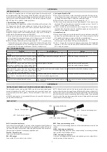
EMERGENCY LOCATOR TRANSMITTER
The airplane is equipped with an emergency locator transmitter which enables to locate it in case of distress. It is
located in fuselage rear section with a service door on fuselage R.H. side.
The emergency locator transmitter assembly is constituted of a transmitter supplied by a battery, of an antenna
attached on upper fuselage and of a remote control located on the upper panel.
NOTE
For test sequences, refer to manufacturer manual.
ELT ARTEX C406--1
Operation of the emergency locator transmitter is obtained as follows :
-
from the instrument panel by setting ”ON/ARM” remote control switch to ”ON” (locator transmitter ”ON/OFF”
switch set to ”OFF”),
-
from the locator transmitter by setting its ”ON/OFF” control switch to ”ON”,
-
automatically in case of shock, when remote control switch is set to ”ARM” and locator transmitter switch is
set to ”OFF”.
A red indicator light located on ”ELT” remote control switch in the cockpit indicates to the pilot the emergency
locator transmitter is transmitting.
A red indicator light located above locator transmitter switch and a buzzer located in the fuselage rear section
indicate the emergency locator transmitter is transmitting.
Reset after an inadvertent activation
1) Set remote control switch or ELT switch to ”ON”. a) The ELT keeps on transmitting emergency signal.
b) On remote control box, red indicator light flashes.
c) On ELT, red indicator light flashes.
d) Near ELT, the buzzer sounds.
2) Wait approximately for 1 second.
3) Set remote control switch to ”ARM” or ELT switch
to ”OFF”.
a) The ELT does not transmit emergency signal any
longer.
b) On
remote
control
box,
red
indicator
light
illuminates for about 1 second, then goes off.
or
c) On ELT, red indicator light goes off.
d) Near ELT, the buzzer does no more sound.
Содержание TBM 900
Страница 349: ...PILOT S OPERATING HANDBOOK SECTION 7 DESCRIPTION Edition 0 October 31 2013 Rev 1 Page 7 2 7 Figure 7 2 2 2 2 WING FLAPS ...
Страница 385: ...PILOT S OPERATING HANDBOOK SECTION 7 DESCRIPTION Edition 0 October 31 2013 Rev 1 Page 7 4 3 Figure 7 4 1 2 2 ROLL ...
Страница 390: ...PILOT S OPERATING HANDBOOK SECTION 7 DESCRIPTION Edition 0 October 31 2013 Rev 1 Page 7 4 8 Figure 7 4 3 2 2 ELEVATOR ...
Страница 395: ...PILOT S OPERATING HANDBOOK SECTION 7 DESCRIPTION Edition 0 October 31 2013 Rev 1 Page 7 4 13 Figure 7 4 5 2 2 RUDDER ...
Страница 398: ...PILOT S OPERATING HANDBOOK SECTION 7 DESCRIPTION Edition 0 October 31 2013 Rev 1 Page 7 4 16 INTENTIONALLY LEFT BLANK ...
Страница 410: ...PILOT S OPERATING HANDBOOK SECTION 7 DESCRIPTION Edition 0 October 31 2013 Rev 1 Page 7 5 12 Figure 7 5 6 PARKING BRAKE ...
Страница 413: ...PILOT S OPERATING HANDBOOK SECTION 7 DESCRIPTION Edition 0 October 31 2013 Rev 1 Page 7 6 3 Figure 7 6 1 2 2 POWERPLANT ...