


5
The ARCUS E is supplied with an ESC featuring the brake function that could
be programmed to stop the spinning of the propeller - this is good for elec-
tric powered motor gliders with a folding prop (Brake On Mode). Or the prop
freely rotates in the idle (Brake Off Mode) - this mode is required for your
ARCUS E (and also suitable for aerobatic planes).
1. Throttle Range Calibration
As the output control signal varies a little bit for different RC set brands, the
ESC features the throttle range calibration. It needs to be performed just
once before the first use of your ESC with a particular transmitter and re-
ceiver.
Also the direction of servo throw is important: the throttle channel of Hitec,
Multiplex, Graupner/HoTT and Pelikan radios has to be set to “NOR(MAL)”,
whilst with the Futaba transmitters to “REV(ERSE)”.
A) Turn on your transmitter, set the the throttle stick to the “full throttle” po-
sition. Connect the power pack to your ESC; the motor emitts “Do Re Mi”
signalling the input voltage is within the acceptable range.
B) After 2 seconds, the motor emitts 2 long beeps (B---- B----) to confirm the
“full throttle” position has been recognized. Pull the throttle stick all the
way down immediately, the ESC will recognize the “motor off” position
and quits the throttle range calibrations. Your ESC is ready to use.
2. Setting the Brake On/Off
A) Turn on your transmitter, set the the throttle stick to the “full throttle” po-
sition. Connect the power pack to your ESC; the motor sounds “Do Re Mi”
signalling the input voltage is within the acceptable range.
B) After 2 seconds, the motor emitts 2 long beeps (B---- B----).
C) After 2 seconds, the motor emitts one short beep (B-). If you want to turn
the brake OFF, pull the throttle stick all the way down now. Your ESC is
ready to use, the brake function disabled.
D) After 2 seconds, the motor emitts two short beeps (B- B-). If you want to
turn the brake ON, pull the throttle stick all the way down now. Your ESC is
ready to use, the brake function enabled.
3. Normal Start-Up
A) Turn on your transmitter, set the the throttle stick to the lowest (motor off)
position. Connect the power pack to your ESC; the motor emitts “Do Re
Mi” signalling the input voltage is within the acceptable range.
B) After 2 seconds, the motor emitts one long beep (B----) to confirm the
throttle stick is in the “Motor OFF” position for safe start.
C) After 2 seconds, the motor emitts either one short beep (B-) if the Brake
function is OFF, or two short beeps (B- B-) if the Brake function is ON. Your
ESC is ready to use now.
SETTING THE ESC
ESC TROUBLESHOOTING
Problem
Possible Reason
Action
After power on, motor does not work, no sound is
emitted
The connection between battery pack and ESC is
not correct
Check the power connection.Replace the connec-
tor.
After power on, motor does not work, such an alert
tone is emitted:“beep-beep-, beep-beep-, beep-
beep-”(Every “beep-beep-” has a time interval of
about 1 second)
Input voltage is abnormal, too high or too low.
Check the voltage of battery pack
After power on, motor does not work, such an
alert tone is emitted:“beep-, beep-, beep- ”(Every
“beep-” has a time interval of about 2 seconds)
Throttle signal is irregular
Check the receiver and transmitter
Check the cable of throttle channel
After power on, motor does not work, such an
alert tone is emitted:“beep-, beep-, beep-” (Every
“beep-” has a time interval of about 0.25 second)
The throttle stick is not in the bottom (lowest) po-
sition
Move the throttle stick to bottom position
After power on, motor does not work, a special
tone “ *56712 ” is emitted after 2 beep tone (beep-
beep-)
Direction of the throttle channel is reversed, so the
ESC has entered the program mode
Set the direction of throttle channel correctly
The motor runs in the opposite direction
The connection between ESC and the motor need
to be changed.
Swap any two wire connections between ESC and
motor
RETRACTABLE POWER UNIT CONTROL MODULE (RMS) MANUAL
The retractable power unit module (RMS) is an electronic device designed
to control (together with an ESC) the operation of a retractable power unit
for electric powered motor gliders. The control module can work in two
modes:
NORMAL - the power unit is extended all the time, the throttle stick controls
just the RPMs of the motor.
AUTO - if the throttle stick is in the lowest position, the power unit is com-
pletely retracted in the fuselage. If you pull the throttle stick up a little bit (2-5
degrees), the power unit will be unfolded from the fuselage. Further pulling
up of the throttle stick will control the RPMs of the motor. If you push the
throttle stick all the way down again, the motor will stop and the power unit
retracts back into the fuselage.
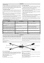
RMS LAYOUT
AUX - Control mode selector
Throttle - Throttle input
ESC - ESC output
RMS - Power unit actuating servo
H-EPA - High endpoint adjuster
L-EPA - Low endpoint adjuster
AUX - Control mode selector
Control modes are selected by 2-position switch assigned to an AUX channel
of your transmitter. The RMS module will work all the time in the AUTO mode,
if you leave the AUX control mode cable of the RMS unconnected (in the case
that your transmitter does not have enough channels).
Throttle - Throttle input
Connect to the receiver throttle output.
ESC - ESC output
Connect the ESC servo cable in this socket.
RMS - Power unit actuating servo
Connect the servo actuating the pylon of the retractable power unit in this
socket.
H-EPA - High endpoint adjuster
It sets the high endpoint of the power unit actuating servo to adjust the up-
right position of unfolded power unit.
L-EPA - Low endpoint adjuster
It sets the low endpoint of the power unit actuating servo to adjust the re-
tracted position of the power unit.
APPENDIX B
APPENDIX A