background image

DGS-3312SR Gigabit Layer 3 Switch 

System Log Server 

Port Security 

SNTP Setting 

Time Setting 

Time Zone and DST 

Access Profile Table 

The DGS-3312SR’s Web interface is divided into six main folders: 

Configuration

Security

Management

Monitoring

Maintenance

, and 

Single IP Management

. This chapter describes all of the 

Configuration

 sub-folders and windows 

except those found in the 

Layer 3 IP Networking

 sub-folder, which are explained in the next chapter, “Advanced 

Configuration.” 

Switch Information 

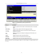
The first page displayed upon logging in is the 

System Information (Basic Settings)

 window. This window can be 

accessed at any time by clicking the 

Switch Information

 button in the 

Configuration

 folder. 


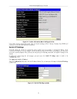
Figure 4- 1.  Switch Information (Basic Settings) window 

This window displays general information about the Switch including its MAC Address, Hardware Boot PROM and 
Firmware versions, and installed module information.  

IP Address 

Switch IP settings may initially be set using the console interface prior to connecting to it through the Ethernet. If the 
Switch IP address has not yet been changed, read the Introduction of the CLI Reference or skip ahead to the end of this 
section for a quick description of how to use the console port and CLI IP settings commands to establish IP settings for the 
Switch. 

To change IP settings using the web manager you must access the 

Switch IP Settings

 window located in the 

Configuration

 folder.  

To configure the Switch’s IP address: 

35 

Содержание DGS-3312SR

Страница 1: ...D Link DGS 3312SR 12 Port Gigabit Layer 3 Stackable Switch Release II Manual Second Edition June 2004 Version 0 2 Printed In Taiwan RECYCLABLE...

Страница 2: ...D Link Computer Corporation is strictly forbidden Trademarks used in this text D Link and the D LINK logo are trademarks of D Link Computer Corporation Microsoft and Windows are registered trademarks...

Страница 3: ...RPS Connector 4 Plug in Modules 4 DEM 340T 1000BASE T Module 4 DEM 340MG SFP Mini GBIC Module 5 DEM 540 IEEE 1394 Stacking Module 5 Switch Stacking 5 Management Options 6 Installation 8 Package Conte...

Страница 4: ...t 26 Admin and User Privileges 26 Save Changes 27 Factory Reset 27 Restart System 28 Advanced Settings 29 Switch Stack Management 30 Configure Stacking 31 Basic Configuration 34 Switch Information 35...

Страница 5: ...er 75 Port Security 77 SNTP Setting 78 Time Setting 78 Time Zone and DST Settings 79 Access Profile Table 80 Advanced Configuration 91 L3 Global Advanced Settings 92 IP Interface Settings 92 MD5 Key S...

Страница 6: ...n 136 Secure Shell SSH 137 SSH Configuration 138 SSH Algorithm 139 SSH User Authentication 141 Access Authentication Control 142 Policy Parameters 143 Application Authentication Settings 144 Authentic...

Страница 7: ...ature 187 Browse IP Address 187 Browse Routing Table 187 Browse ARP Table 188 Browse IP Multicast Forwarding Table 189 Browse IGMP Group Table 190 OSPF Monitor 190 Browse OSPF LSDB Table 190 Browse OS...

Страница 8: ...M Settings 201 Topology 202 Tool Tips 205 Right click 206 Group Icon 206 Commander Switch Icon 207 Member Switch Icon 208 Candidate Switch Icon 209 Menu Bar 210 Group 211 Device 211 View 211 Firmware...

Страница 9: ...opy followed by the name of the file Do not type the brackets Bold font Indicates a button a toolbar icon menu or menu item For example Open the File menu and choose Cancel Used for emphasis May also...

Страница 10: ...r cable extension cable or plug is damaged An object has fallen into the product The product has been exposed to water The product has been dropped or damaged The product does not operate correctly wh...

Страница 11: ...plugs Consult a licensed electrician or your power company for site modifications Always follow your local national wiring rules When connecting or disconnecting power to hot pluggable power supplies...

Страница 12: ...if you are uncertain that suitable grounding is available CAUTION The system chassis must be positively grounded to the rack cabinet frame Do not attempt to connect power to the system until groundin...

Страница 13: ...DGS 3312SR Gigabit Layer 3 Switch xii...

Страница 14: ...ck up to eight additional Switches IEEE 1394 or up to eight additional Gigabit Ethernet ports 1000BASE T or SFP or use combination of stacking and Gigabit Ethernet ports Star topology Switch stacking...

Страница 15: ...nt panel of the Switch consists of LED indicators an RS 232 communication port two slide in module slots and four 1000BASE T SFP combo ports Figure 1 1 Front Panel View of the Switch as shipped no mod...

Страница 16: ...ssion i e Activity Act of data occurring at a port See below for description of Stack ID LED indicator NOTICE The Stack ID LED on the Switch s front panel will display an F regardless of the Switch s...

Страница 17: ...ower connector is a standard three pronged connector that supports the power cord Plug in the female connector of the provided power cord into this socket and the male side of the cord into a power ou...

Страница 18: ...option is to use the built in combination ports 1000BASE T SFP The other possibility is to install one or two DEM 540 stacking modules and complete the stacking connection through the IEEE 1394 stack...

Страница 19: ...3312SR is slightly different from the CLI stacking command set for the DES 3226S Please refer to the CLI Reference Manual for each Switch for details or read the instructions starting on page 12 below...

Страница 20: ...C 2233 IF MIB RFC 2358 Ethernet Link MIB RFC 2573 SNMP Notification and Target MIB RFC 2574 SNMP User based SM MIB RFC 2575 SNMP View based ACM MIB RFC 2674 802 1p and 802 1q Bridge MIB RFC 2737 Entit...

Страница 21: ...e AC power cord This Manual CLI Reference Before You Connect to the Network Before you connect to the network you must install the Switch on a flat surface or in a rack set up a terminal emulation pro...

Страница 22: ...with or without a rack Installing the Switch in a Rack You can install the Switch in most standard 19 inch 48 3 cm racks Refer to the illustrations below 1 Use the supplied screws to attach a mounting...

Страница 23: ...stacked group of DES 3226S Switches are connected using a star topology The instructions below Configuring a Switch Group for Stacking tell you how to configure the DGS 3312SR to function as a Master...

Страница 24: ...s with IEEE 1394 and Ethernet Cabling Figure 2 4 Star Topology Stacked Switch Group The stacking ports are marked IN and OUT The IEEE 1394 compliant cable must be connected from an IN port on one Swit...

Страница 25: ...e verified by a Success message It takes a few seconds for the change to take effect and be saved See the example below for the DES 3226S DES 3226S 4 config stacking mode enable auto Command config st...

Страница 26: ...th port 1 from left to right along the front panel of the Switch For example the four combination ports next to the Stack NO LED are numbered 1 through 4 so if a four port stacking module is installed...

Страница 27: ...owing equipment A terminal or a computer with both a serial port and the ability to emulate a terminal A null modem or crossover RS 232 cable with a female DB 9 connector for the console port on the S...

Страница 28: ...mation on setting up user accounts See the Command Line Reference on the documentation CD for a list of all commands and additional information on using the CLI k When you have completed your tasks ex...

Страница 29: ...e SNMP versions 1 2c and 3 You can specify which version of the SNMP you want to use to monitor and control the Switch The three versions of SNMP vary in the level of security provided between the man...

Страница 30: ...ng the MIB Object Identifier MIB values can be either read only or read write IP Address Assignment Each Switch must be assigned its own IP Address which is used for communication with an SNMP network...

Страница 31: ...IP address of 10 22 24 9 with a subnet mask of 255 0 0 0 The system message Success indicates that the command was executed successfully The Switch can now be configured and managed via Telnet and th...

Страница 32: ...the Intranet Its function in a network can be thought of as a new generation of router that performs routing functions in hardware rather than software It is in effect a router that also has numerous...

Страница 33: ...l resources can save valuable time in case of a link or device failure The DGS 3312SR Spanning Tree function can be used to block the redundant link until it is needed VLAN Setup VLANs setup in Layer...

Страница 34: ...on or view data for the port 2 Select the window to be displayed The folder icons can be opened to display the hyperlinked window buttons and sub folders contained within them 3 Presents the informati...

Страница 35: ...ment The windows used to configure SNMP settings management IP stations and user accounts are located here Monitoring This folder includes stack information and data tables for performance statistics...

Страница 36: ...e Switch IP address has not yet been changed read the Introduction of the CLI Reference or skip ahead to the end of this section for a quick description of how to use the console port and CLI IP setti...

Страница 37: ...ption is set the Switch will first look for a BOOTP server to provide it with this information before using the default or previously entered settings DHCP The Switch will send out a DHCP broadcast re...

Страница 38: ...ress xxx xxx xxx xxx yyy yyy yyy yyy Where the x s represent the IP address to be assigned to the IP interface named System and the y s represent the corresponding subnet mask Alternatively you can en...

Страница 39: ...the same password in the Confirm New Password Choose the level of privilege Admin or User from the Access Right drop down menu Figure 3 7 User Account Modify Table window Modify or delete an existing...

Страница 40: ...he Switch has two levels of memory normal RAM and non volatile or NV RAM To save all the changes made in the current session to the Switch s flash memory click the Save Configuration button Click the...

Страница 41: ...ngs but does not save the settings or reboot the Switch If you select this option the Switch configuration will be returned to the factory default settings and then saves the factory default configura...

Страница 42: ...tart System window NOTE Clicking Yes is equivalent to executing Save Changes and then restarting the Switch Advanced Settings Figure 3 11 Switch Information Advanced Settings window The Advanced Setti...

Страница 43: ...iguration is Enabled by default If you do not want to allow configuration of the system through Telnet choose Disabled Telnet TCP Port Number 1 65535 The Telnet TCP port number TCP ports are numbered...

Страница 44: ...tch stack is displayed in the Stack Mode Setup window To view stacking information or to enable disable the stacking mode click the Stack Information link in the Configuration folder Figure 3 12 Stack...

Страница 45: ...plays the total number of ports on the Switch Note that the stacking port is included in the total count Mode Displays the method used to determine the stacking order of the Switches in the Switch sta...

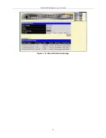
Страница 46: ...DGS 3312SR Gigabit Layer 3 Switch Figure 3 14 Stack Information web page 33...

Страница 47: ...X Authenticator Settings PAE System Control 802 1X Capability Settings RADIUS Server IGMP IGMP Snooping Static Router Ports Entry Spanning Tree STP Switch Settings STP Port Settings Forwarding Filteri...

Страница 48: ...icking the Switch Information button in the Configuration folder Figure 4 1 Switch Information Basic Settings window This window displays general information about the Switch including its MAC Address...

Страница 49: ...at will access the Switch The Switch will allow management access from stations with the same VID listed here To use the BOOTP or DHCP protocols to assign the Switch an IP address subnet mask and defa...

Страница 50: ...ch until either Management Station IP Addresses are assigned or SNMP settings are configured to control management access Setting the Switch s IP Address using the Console Interface Each Switch must b...

Страница 51: ...d specifies the length of time a learned MAC Address will remain in the forwarding table without being accessed that is how long a learned MAC Address is allowed to remain idle The default age out tim...

Страница 52: ...to connect to the web interface The well known TCP port for the Web interface is 80 RMON Status Remote monitoring RMON of the Switch is Enabled or Disabled here GVRP Use this pull down menu to enable...

Страница 53: ...DGS 3312SR Gigabit Layer 3 Switch 40...

Страница 54: ...ort to automatically determine the fastest settings the device the port is connected to can handle and then to use those settings The other options are 1000M Full 1000M Half 100M Full 100M Half 10M Fu...

Страница 55: ...of a Switch in a Switch stack The number 15 indicates a DGS 3312SR Switch in standalone mode From To A consecutive group of ports may be configured starting with the selected port Description Enter a...

Страница 56: ...NOTE You cannot mirror a fast port onto a slower port For example if you try to mirror the traffic from a 100 Mbps port onto a 10 Mbps port this can cause throughput problems The port you are copying...

Страница 57: ...e Default setting is 128 Link Aggregation The Switch allows the creation of up to six link aggregation groups each group consisting of up of up to eight links ports The aggregated links must be contig...

Страница 58: ...ation Figure 4 8 Port Trunking group window To configure port trunk groups click the Add button to add a new trunk group and then use the Port Trunking Configuration window below to set up trunk group...

Страница 59: ...of the trunked group Up to eight ports per group can be assigned to a group Flooding Port A trunking group must designate one port to allow transmission of broadcasts and unknown unicasts Active Port...

Страница 60: ...e Both devices must support LACP Passive LACP ports that are designated as passive cannot initially send LACP control frames In order to allow the linked port group to negotiate adjustments and make c...

Страница 61: ...uration with User Authentication The user s information including account number password and configuration details such as IP address and billing information is stored in a centralized RADIUS server...

Страница 62: ...achine Table 4 1 Conformance to IEEE 802 1X Standards 802 1X Authenticator Settings To display the current 802 1X Authenticator Settings on the Switch open the Port Access Entity folder and click on t...

Страница 63: ...without any authentication exchange required This means the port transmits and receives normal traffic without 802 1X based authentication of the client If Force_unauthorized is selected the port wil...

Страница 64: ...eAuth Enable or disable reauthentication PAE System Control To set the port authenticating settings open the Port Access Entity folder and then the PAE System Control folder Finally click on the 802 1...

Страница 65: ...UDP port on the RADIUS server that will be used to log authentication events The default is 1813 Key Type the shared secret key used by the RADIUS server and the Switch Up to 32 characters can be used...

Страница 66: ...AN ID you want to change Figure 4 18 Current IGMP Snooping Group Entries window Click the Modify button to bring up the IGMP Snooping Settings window pictured below Figure 4 19 IGMP Snooping Settings...

Страница 67: ...ceived before the Leave Timer expires the multicast forwarding entry for that host is deleted Querier State Choose Enabled to enable transmitting IGMP Query packets The default value is Disabled State...

Страница 68: ...2 1d Spanning Tree Protocol STP and 802 1w Rapid Spanning Tree Protocol RSTP 802 1d STP will be familiar to most networking professionals However since 802 1w RSTP has been recently introduced to D Li...

Страница 69: ...tion to a forwarding state it no longer relies on timer configurations RSTP compliant bridges are sensitive to feedback from other RSTP compliant bridge links Ports do not need to wait for the topolog...

Страница 70: ...tch Bridge Max Age 6 40 sec 20 The Max Age can be set from 6 to 40 seconds At the end of the Max Age if a BPDU has still not been received from the Root Bridge your Switch will start sending its own B...

Страница 71: ...or Stp Compatibility Both versions use STP parameters in the same way RSTP is fully compatible with IEEE 802 1d STP and will function with legacy equipment Tx Hold Count 1 10 3 This is the maximum nu...

Страница 72: ...umber the greater the probability the port will be chosen to forward packets Default port cost 100Mbps port 200000 Gigabit ports 20000 Priority A Port Priority can be from 0 to 240 The lower the numbe...

Страница 73: ...the module on which the above MAC address resides Port Choose the port on which the MAC address resides Selecting Port 0 means no ports are allowed Click on the Add Modify button to add a unicast MAC...

Страница 74: ...P Switching among VLANs may be unfamiliar to users who are otherwise well acquainted with conventional VLANs used in standard Ethernet Switches some explanation of VLANs used in Layer 3 Switching is p...

Страница 75: ...standard VLANs operate according to the same rules regardless of whether the Switching environment is Layer 2 or Layer 3 The difference is primarily that in a Layer 3 Switch there is an added capabil...

Страница 76: ...g Token Ring packets so they can be carried across Ethernet backbones and twelve bits of VLAN ID VID The three bits of user priority are used by 802 1p The VID is the VLAN identifier and is used by th...

Страница 77: ...is not used to make packet forwarding decisions the VID is Tag aware Switches must keep a table to relate PVIDs within the Switch to VIDs on the network The Switch will compare the VID of a packet to...

Страница 78: ...e Switch then determines if the destination port is a member of the same VLAN has the same VID as the ingress port If it does not the packet is dropped If it has the same VID the packet is forwarded a...

Страница 79: ...VLAN entry type in a unique identifier This number is used to configure other settings such as GVRP status for ports in the VLAN VLAN Name For a new VLAN entry type in a unique name This name can be...

Страница 80: ...ge the port settings of any listed VLAN click the Modify button Now click the Modify button in the first 802 1Q Static VLANs window for the newly created VLAN engineering A new window appears use this...

Страница 81: ...gs window Configure the 802 1 Port Settings Parameter Description Unit Select the relevant Switch for configuration From To Use these drop down menus to specify the range of ports that will be include...

Страница 82: ...kets The Switch implements 802 1p priority using eight hardware queues Therefore the Switch must have a means of mapping the eight levels specified in the IEEE 802 1p standard to the eight hardware qu...

Страница 83: ...ity queues are numbered from 0 the lowest priority to 7 the highest priority 802 1p User Priority The DGS 3312SR allows the assignment of a User Priority to each of the 802 1p priorities Figure 4 37 U...

Страница 84: ...as bottlenecks can quickly develop if the QoS settings are not suitable Figure 4 38 QoS Output Scheduling Configuration window Use the Scheduling Mechanism drop down menu to select between a RoundRobi...

Страница 85: ...ou to select a Switch from a Switch stack using that Switch s Unit ID The Port drop down menu allows you to select a port from that Switch This is the port that will be transmitting packets Bandwidth...

Страница 86: ...menu allows you to select between RX receive TX transmit and Both This setting will determine whether the bandwidth ceiling is applied to receiving transmitting or both receiving and transmitting pack...

Страница 87: ...following parameters can be set Parameter Description State This drop down menu is used to enable or disable MAC notification on the selected Switch Interval sec The time in seconds between notificati...

Страница 88: ...Switch stack using that Switch s Unit ID Number 15 indicates a Switch in standalone mode From To A consecutive group of ports may be configured starting with the selected port State This pull down men...

Страница 89: ...s drop down menu allows you to select the level of messages that will be sent The options are Warning Informational and ALL Facility Some of the operating system daemons and processes have been assign...

Страница 90: ...led to activate or deactivate this Port Security A given port s or a range of port s dynamic MAC address learning can be locked such that the current source MAC addresses entered into the MAC address...

Страница 91: ...ses that will be in the MAC address forwarding table for the selected Switch and group of ports Lock Address Mode This pull down menu allows you to select how the MAC address table locking will be imp...

Страница 92: ...he interval between requests for updated SNTP information Year Enter the current year if you want to update the system clock Month Enter the current month if you want to update the system clock Day En...

Страница 93: ...hat Time HH MM Enter the time of day that DST will start on To Which Week Enter the week of the month the DST will end To Which Day Enter the day of the week that DST will end To Which Month Enter the...

Страница 94: ...rofile configuration one for IP address based profile configuration and one for Packet Content Mask based profile configuration You can Switch among the three Access Profile Configuration windows by u...

Страница 95: ...examine the 802 1p priority value of each packet header and use this as the or part of the criterion for forwarding Ethernet type Selecting this option instructs the Switch to examine the Ethernet ty...

Страница 96: ...eader You must then specify what protocol s to include according to the following guidelines Select ICMP to instruct the Switch to examine the Internet Control Message Protocol ICMP field in each fram...

Страница 97: ...gure 4 51 Access Profile Configuration Packet Content Mask window This window will aid the user in configuring the Switch to mask packet headers beginning with the offset value specified The following...

Страница 98: ...value 16 31 Enter a value in hex form to mask the packet from byte 16 to byte 31 value 32 47 Enter a value in hex form to mask the packet from byte 32 to byte 47 value 48 63 Enter a value in hex form...

Страница 99: ...ntifier number for this access This value can be set from 1 to 255 Type Select profile based on Ethernet MAC Address IP address or packet content mask This will change the menu according to the requir...

Страница 100: ...estination MAC address 802 1p 0 7 Enter a value from 0 to 7 to specify that the access profile will apply only to packets with this 802 1p priority value Ethernet Type Specifies that the access profil...

Страница 101: ...the packet header Priority 0 7 Specify the priority tag located in the packet header that will be identified by the Switch Replace Dscp with 0 63 Select this option to instruct the Switch to replace...

Страница 102: ...Access Rule Configuration Package Content Mask window Configure the Access Rule Configuration settings on the window above The following parameters can be set Parameter Description Profile ID This is...

Страница 103: ...me s header Select Packet Content Mask to specify a mask to hide the content of the packet header Priority 0 7 Specify the priority tag located in the packet header that will be identified by the Swit...

Страница 104: ...eneral Setting OSPF Area ID Settings OSPF Interface Settings OSPF Virtual Interface Settings OSPF Area Aggregation Settings OSPF Host Route Settings DHCP BOOTP Relay DHCP BOOTP Relay Information DHCP...

Страница 105: ...o remain in the ARP dynamic entry table To setup permanent entries for ARP use the Static ARP Settings window described later in this chapter NOTE PIM RIP OSPF and DVMRP may also be globally enabled o...

Страница 106: ...nter it in the Interface Name field if you are editing an IP Interface the Interface Name will already be in the top field as seen in the window above Enter the interface s IP address and subnet mask...

Страница 107: ...estinations known to the router The following is a simplified description of the algorithm s steps 1 When OSPF is started or when a change in the routing information changes the router generates a lin...

Страница 108: ...alculated Figure 5 5 Constructing a Shortest Path Tree Router A Router B Router C Router D 128 213 0 0 192 213 11 0 222 211 10 0 0 10 10 5 5 10 10 Figure 5 6 Constructing a Shortest Path Tree The diag...

Страница 109: ...ables Areas establish boundaries beyond which link state updates do not need to be flooded So the exchange of link state updates and the calculation of the shortest path tree are limited to the area t...

Страница 110: ...exchanged over the wire and a non decreasing sequence number is included to prevent replay attacks Simple Password Authentication A password or key can be configured on a per area basis Routers in th...

Страница 111: ...k state database exchange process OSPF elects one router as the Designated Router DR and a second router as the Backup Designated Router BDR on each multi access segment the BDR is a backup in case of...

Страница 112: ...h a standard 24 byte header and there are five packet types The header is described first and each packet type is described in a subsequent section All OSPF packets except for Hello packets forward li...

Страница 113: ...e sent periodically on all interfaces including virtual links in order to establish and maintain neighbor relationships In addition Hello Packets are multicast on those physical networks having a mult...

Страница 114: ...ddress on the network This field is set to 0 0 0 0 if there is no BDR Field Description Neighbor The Router Ids of each router from whom valid Hello packets have been seen within the Router Dead Inter...

Страница 115: ...n packets with a neighboring router a router may find that parts of its topological database are out of date The Link State Request packet is used to request the pieces of the neighbor s database that...

Страница 116: ...Link State Update Packet The body of the Link State Update packet consists of a list of link state advertisements Each advertisement begins with a common 20 byte header the link state advertisement he...

Страница 117: ...ements may also be originated The flooding algorithm is reliable ensuring that all routers have the same collection of link state advertisements The collection of advertisements is called the link sta...

Страница 118: ...Link State ID This field identifies the portion of the internet environment that is being described by the advertisement The contents of this field depend on the advertisement s Link State Type Adver...

Страница 119: ...o calculate a separate set of routes for each IP Type of Service TOS Router links advertisements are flooded throughout a single area only Field Description V bit When set the router is an endpoint of...

Страница 120: ...o of TOS The number of different Type of Service TOS metrics given for this link not counting the required metric for TOS 0 If no additional TOS metrics are given this field should be set to 0 TOS 0 M...

Страница 121: ...ement is made for each destination known to the router that belongs to the Autonomous System AS yet is outside the area Type 3 link state advertisements are used when the destination is an IP network...

Страница 122: ...xternal link advertisements usually describe a particular external destination For these advertisements the Link State ID field specifies an IP network number AS external link advertisements are also...

Страница 123: ...n 5 MD5 key that can be used to authenticate every packet exchanged between OSPF routers It is used as a security mechanism to limit the exchange of network topology information to the OSPF routing do...

Страница 124: ...omplished by comparing the routes stored in the various routers routing tables and assigning appropriate metrics This information is then exchanged among the various routers according to the individua...

Страница 125: ...es the metric entered in the Metric field without change This field applies only when the destination field is OSPF Metric Allows the entry of an interface cost Static Default Route Settings Static ro...

Страница 126: ...y click on the Add button a new window appears see below To remove an existing entry click the X button in the Delete column for the entry you want to eliminate To delete all static ARP entries click...

Страница 127: ...for RIP to the following window Figure 5 28 RIP Interface Settings Edit window Refer to the table below for a description of the available parameters for RIP interface settings To return to the RIP In...

Страница 128: ...eral Setting link To enable OSPF first supply an OSPF Route ID see below select Enabled from the State drop down menu and click the Apply button Figure 5 29 OSPF General Setting window The following p...

Страница 129: ...k the X in the Delete column for the configuration To change an existing set in the list type the Area ID of the set you want to change make the changes and click the Add Modify button The modified OS...

Страница 130: ...ear listed To change settings for in IP interface click on the hyperlinked name of the interface to see the configuration menu for that interface Figure 5 32 OSPF Interface Settings window Figure 5 33...

Страница 131: ...uthorization schemes for OSPF packets that may be exchanged over the OSPF routing domain None specifies no authorization Simple uses a simple password to determine if the packets are from an authorize...

Страница 132: ...s Enter a value between 1 and 65535 seconds The Hello Interval Dead Interval Authorization Type and Authorization Key should have identical settings for all routers on the same network Dead Interval 1...

Страница 133: ...r the configuration being removed Figure 5 36 OSPF Area Aggregation Settings window Use the window below to change settings or add a new Area Aggregation setting Figure 5 37 OSPF Aggregation Configura...

Страница 134: ...ting configuration click the X in the Delete column for the configuration being removed Figure 5 38 OSPF Host Route Settings window Use the window below to set up OSPF host routes Figure 5 39 OSPF Hos...

Страница 135: ...ill relay the BOOTP packet To configure BOOTP relay for individual IP interfaces use the following window DHCP Bootp Relay Settings Figure 5 41 DHCP Bootp Relay Settings window To create a new relay c...

Страница 136: ...dress of the secondary DNS server DNSR Cache Status Use this to enable the DNS relay cache function The DNS cache relay can be used to temporarily store DNS relay information for faster recall DNSR St...

Страница 137: ...with the highest priority to be the Master router on the LAN This retains the link and the connection is kept alive regardless of the point of failure To configure VRRP for virtual routers on the Swit...

Страница 138: ...selected to compare VRRP packets received by a virtual router Simple Text Password A Simple password has been selected to compare VRRP packets received by a virtual router for authentication IP Authe...

Страница 139: ...nable Up and disable Down the VRRP IP interface on the Switch Priority 1 255 Enter a value between 1 and 255 to indicate the router priority The VRRP Priority value may determine if a higher priority...

Страница 140: ...e or disable the Critical IP address entered above Auth Type Specifies the type of authentication used The Auth Type must be consistent with all routers participating within the VRRP group The choices...

Страница 141: ...d has been selected to compare VRRP packets received by a virtual router for authentication IP Authentication Header An MD5 message digest algorithm has been selected to compare VRRP packets received...

Страница 142: ...up router if the routers priority is set higher than the master router False will disable the backup router from becoming the master router Virtual Router Up Time Displays the time in minutes since th...

Страница 143: ...MP queries on the interface Query Interval 1 65535 125 Allows the entry of a value between 1 and 65535 seconds with a default of 125 seconds This specifies the length of time between sending IGMP quer...

Страница 144: ...hange DVMRP Interface Settings To configure existing IP interfaces on the Switch for DVMRP use the DVMRP Interface Settings window Figure 5 51 1st DVMRP Interface Settings window DVMRP settings can be...

Страница 145: ...hop count in RIP The default cost is 1 State Disabled This field can be toggled between Enabled and Disabled and enables or disables DVMRP for the IP interface The default is Disabled PIM For a descr...

Страница 146: ...erface IP Address Displays the IP address for the IP interface named above Hello Interval 30 This field allows an entry of between 0 and 18724 seconds and determines the interval between sending Hello...

Страница 147: ...Admin Trusted Host The Security IP Management window allows you to specify the IP addresses of management stations PCs on your network that will be allowed to access the Switch s Web based management...

Страница 148: ...timal use CBC Block Ciphers CBC refers to Cipher Block Chaining which means that a portion of the previously encrypted block of encrypted text is used in the encryption of the current block The switch...

Страница 149: ...nes the exact cryptographic parameters specific encryption algorithms and key sizes to be used for an authentication session The switch possesses four possible ciphersuites for the SSL function which...

Страница 150: ...its functions see the DGS 3312SR Command Line Reference Manual located on the documentation CD of this product NOTE Enabling the SSL command will disable the web based switch management To log on to...

Страница 151: ...tion SSH Configuration The following window is used to configure and view settings on the SSH server and can be opened by clicking Security Secure Shell SSH SSH Configuration Figure 6 4 Current SSH Co...

Страница 152: ...e security shell encryptions by using the pull down menu The options are Never 10 min 30 min and 60 min The default setting is Never Port 1 65535 Enter the TCP port number associated with this functio...

Страница 153: ...wn menu to enable or disable the Cast128 encryption algorithm with Cipher Block Chaining The default is Enabled Twofish128 Use the pull down menu to enable or disable the twofish128 encryption algorit...

Страница 154: ...heTrinity has been previously set using the User Accounts window in the Management folder A user account MUST be set in order to set the parameters for the SSH user To configure the parameters for the...

Страница 155: ...otocol for packet transmission Extended TACACS XTACACS An extension of the TACACS protocol with the ability to provide more types of authentication requests and more types of response codes than TACAC...

Страница 156: ...CACS XTACACS and TACACS are separate entities and are not compatible The switch and the server must be configured exactly the same using the same protocol For example if the switch is set up for TACAC...

Страница 157: ...List configured by the user See the Login Method List Settings window in this section for more information Enable Method List Using the pull down menu configure an application for normal login on the...

Страница 158: ...r Host Settings window before adding hosts to the list Authentication Server Hosts must be configured for their specific protocol on a remote centralized server before this function can work properly...

Страница 159: ...t the user wishes to add Protocol The protocol used by the server host The user may choose one of the following TACACS Enter this parameter if the server host utilizes the TACACS protocol XTACACS Ente...

Страница 160: ...ost in the server group and so on until the list is exhausted At that point the Switch will restart the same sequence with the following protocol listed XTACACS If no authentication takes place using...

Страница 161: ...the user to be authenticated using the local user account database on the switch none Adding this parameter will require no authentication to access the switch radius Adding this parameter will requir...

Страница 162: ...If no verification is found the Switch will send an authentication request to the second TACACS host in the server group and so on until the list is exhausted At that point the Switch will restart th...

Страница 163: ...meter will require the user to be authenticated using the RADIUS protocol from a remote RADIUS server tacacs Adding this parameter will require the user to be authenticated using the TACACS protocol f...

Страница 164: ...the Switch users will have only user level privileges To gain access to administrator level privileges the user will open this window and will have to enter an authentication password Possible authen...

Страница 165: ...DGS 3312SR Gigabit Layer 3 Switch Figure 6 22 Enter Network Password dialog box 152...

Страница 166: ...nt Management to control user privileges To view existing User Accounts open the Management folder and click on the User Accounts link This will open the User Account Management window as shown below...

Страница 167: ...Management Admin User Configuration Yes Read Only Network Monitoring Yes Read Only Community Strings and Trap Stations Yes Read Only Update Firmware and Configuration Files Yes No System Utilities Yes...

Страница 168: ...n existing SNMP User Table entry click on the X icon below the Delete heading corresponding to the entry you want to delete SNMP User Table Display To display the detailed entry for a given user click...

Страница 169: ...ow SNMP User Table Configuration Figure 7 6 SNMP User Table Configuration window The following parameters can set Parameter Description User Name An alphanumeric string of up to 32 characters This is...

Страница 170: ...separate window will appear SNMP View Table Configuration Figure 7 8 SNMP View Table Configuration window The SNMP Group created with this table maps SNMP users identified in the SNMP User Table windo...

Страница 171: ...e previous window Figure 7 9 SNMP Group Table window To delete an existing SNMP Group Table entry click the corresponding X icon under the Delete heading SNMP Group Table Display To display the curren...

Страница 172: ...includes improvements in the Structure of Management Information SMI and adds some security features SNMPv3 Specifies that the SNMP version 3 will be used SNMP v3 provides secure access to devices thr...

Страница 173: ...s SNMP agent View Name Type an alphanumeric string of up to 32 characters that is used to identify the group of MIB objects that a remote SNMP manager is allowed to access on the Switch The view name...

Страница 174: ...ype the IP address of the remote management station that will serve as the SNMP host for the Switch SNMP Version V1 Specifies that SNMP version 1 will be used V2c Specify that SNMP version 2c will be...

Страница 175: ...folder and then the SNMPV3 folder Finally click on the SNMP Engine ID link This will open the SNMP Engine ID Configuration window as shown below Figure 7 15 SNMP Engine ID Configuration window To chan...

Страница 176: ...nooping Browse Router Port VLAN Status Session Table Layer 3 Feature Browse IP Address Table Browse Routing Table Browse ARP Table Browse IP Multicast Forwarding Table Browse IGMP Group Table OSPF Mon...

Страница 177: ...ight additional slave Switch units The web manager can be used to enable or disable the stacking mode and to enable stacking for any of the built in combination ports The Switch stack displayed in the...

Страница 178: ...r Description ID Displays the Switch s order in the stack The Switch with a unit id of 1 is the master Switch MAC Address Displays the unique address of the Switch assigned by the factory Port Range D...

Страница 179: ...ck Information web page Port Utilization The Port Utilization window displays the percentage of the total available bandwidth being used on the port To view the port utilization click on the Monitorin...

Страница 180: ...ndalone mode Port Allows you to specify a port to monitor from the Switch selected above Clear Clicking this button clears all statistics counters on this window Time Interval 1s Select the desired se...

Страница 181: ...can be set Parameter Description Time Interval 1s Select the desired setting between 1s and 60s where s stands for seconds The default value is one second Record Number 200 Select number of times the...

Страница 182: ...DGS 3312SR Gigabit Layer 3 Switch Received Packets Figure 8 6 Rx Packets Analysis line graph for Bytes Packets window 169...

Страница 183: ...ort to monitor from the Switch selected above Clear Clicking this button clears all statistics counters on this window View Table Clicking this button instructs the Switch to display a table rather th...

Страница 184: ...DGS 3312SR Gigabit Layer 3 Switch Received Unicast Multicast Broadcast Packets Figure 8 8 Rx Packets Analysis line graph for Unicast Multicast Broadcast window 171...

Страница 185: ...bove Clear Clicking this button clears all statistics counters on this window View Table Clicking this button instructs the Switch to display a table rather than a line graph View Line Chart Clicking...

Страница 186: ...3312SR Gigabit Layer 3 Switch Show Hide Check whether or not to display Multicast Broadcast and Unicast Packets Transmitted Packets Figure 8 10 Tx Packets Analysis line graph for Bytes Packets window...

Страница 187: ...y a port to monitor from the Switch selected above Clear Clicking this button clears all statistics counters on this window View Table Clicking this button instructs the Switch to display a table rath...

Страница 188: ...312SR Gigabit Layer 3 Switch Errors Various statistics can be viewed as either a line graph or a table Received Errors Transmitted Errors Received Errors Figure 8 12 Rx Error Analysis line graph windo...

Страница 189: ...itch to display a table rather than a line graph View Line Chart Clicking this button instructs the Switch to display a line graph rather than a table CrcError Counts otherwise valid frames that did n...

Страница 190: ...The time between updates received from the Switch in seconds The default is 1s Record Number 200 Select number of times the Switch will be polled between 20 and 200 The default value is 200 Show Hide...

Страница 191: ...a line graph View Line Chart Clicking this button instructs the Switch to display a line graph rather than a table ExDefer Excessive Deferral The number of frames for which the first transmission atte...

Страница 192: ...be polled between 20 and 200 The default value is 200 Show Hide Check whether to display ExDefer LateColl ExColl SingColl and Coll errors Size Various statistics can be viewed as either a line graph...

Страница 193: ...king this button instructs the Switch to display a line graph rather than a table 64 The total number of packets including bad packets received that were 64 octets in length excluding framing bits but...

Страница 194: ...1s Record Number 200 Select number of times the Switch will be polled between 20 and 200 The default value is 200 Show Hide Check whether or not to display 64 65 127 128 255 256 511 512 1023 and 1024...

Страница 195: ...igure 8 18 MAC Address Table window The following fields can be set Parameter Description VLAN ID Allows you to enter a VLAN ID MAC Address Allows you to specify a MAC Address Unit Port Enter the desi...

Страница 196: ...nected to the console manager Clicking Next at the bottom of the window will allow you to display all the switch Trap Logs The information is described as follows Parameter Description Sequence A coun...

Страница 197: ...Snooping Table window The following field can be set Parameter Description Multicast Group The IP address of the multicast group MAC Address The MAC address of the multicast group Reports The total nu...

Страница 198: ...DGS 3312SR Gigabit Layer 3 Switch Figure 8 21 Browse Router Port window VLAN Status This window displays the status of VLANs on any Switch in a Switch stack managed by a DGS 3312SR 185...

Страница 199: ...S 3312SR Gigabit Layer 3 Switch Figure 8 22 VLAN Status window Session Table This window displays the management sessions since the Switch was last rebooted Figure 8 23 Current Session Table window 18...

Страница 200: ...e Switch To search a specific IP address enter it into the field labeled IP Address at the top of the screen and click Find to begin your search Figure 8 24 IP Address window Browse Routing Table The...

Страница 201: ...ARP Table The ARP Table window may be found in the Monitoring folder in the Layer 3 Feature sub folder This window will show current ARP entries on the Switch To search a specific ARP entry enter an i...

Страница 202: ...Multicast Forwarding Table window may be found in the Monitoring folder in the Layer 3 Feature sub folder This window will show current IP multicasting information on the Switch To search a specific e...

Страница 203: ...dows regarding OSPF Open Shortest Path First information on the Switch including the OSPF LSDB Table OSPF Neighbor Table and the OSPF Virtual Neighbor Table To view these tables open the Monitoring fo...

Страница 204: ...nk in the LSDB Type field and then click Find The following fields are displayed Parameter Description Area ID Allows the entry of an OSPF Area ID This Area ID will then be used to search the table an...

Страница 205: ...h the backbone area 0 A Transit Area cannot be a Stub Area or a Backbone Area Neighbor ID The OSPF router ID for the remote router This IP address uniquely identifies the remote area s Area Border Rou...

Страница 206: ...lticast packets on outgoing interfaces Each entry in the DVMRP Routing Next Hop Table window refers to the next hop of a specific source to a specific multicast group address This table is found in th...

Страница 207: ...f a router s PIM neighbors This window may be found in the Monitoring folder in the Layer 3 Feature sub folder under the heading PIM Monitor You may define your search by entering an Interface Name an...

Страница 208: ...r and then the Download Firmware link Figure 9 1 Download Firmware window Use the Unit Number drop down menu to select which Switch of a Switch stack you want to update the firmware on This allows the...

Страница 209: ...ngs To TFTP Server window Enter the IP address of the TFTP server and the path and filename for the history log on the TFTP server Click Apply to make the changes current Click Start to initiate the f...

Страница 210: ...ore rebooting the Switch Save Changes To retain any configuration changes permanently click the Save Configuration button in window below Figure 9 6 Save Configuration window Once the Switch configura...

Страница 211: ...e last saved configuration when rebooted In addition the Reset System option is added to reset all configuration parameters to their factory defaults save these parameters to the Switch s non volatile...

Страница 212: ...SR Gigabit Layer 3 Switch Figure 9 8 Restart System window Logout Use this window to logout of the Switch s Web based management agent by clicking on the Log Out button Figure 9 9 Logout Web Setups wi...

Страница 213: ...a Candidate Switch CaS which is a Switch that has a physical link to the SIM group but has not been recognized by the CS as a member of the SIM group A SIM group can only have one Commander Switch CS...

Страница 214: ...ually configuring the switch to be a MS The CS will then serve as the in band entry point for access to the MS The CS s IP address will become the path to all MS s of the group and the CS s Administra...

Страница 215: ...rval in seconds that the Switch will send out discovery packets Returning information to a Commander Switch will include information about other switches connected to it Ex MS CaS The user may set the...

Страница 216: ...six digits of the MAC Address to identify it Local Port Displays the number of the physical port on the CS that the MS or CaS is connected to The CS will have no entry in this field Speed Displays the...

Страница 217: ...hin the Single IP Management Group are connected to other groups and devices Possible icons in this screen are as follows Icon Description Group Layer 2 commander switch Layer 3 commander switch Comma...

Страница 218: ...viewing device information Setting the mouse cursor over a specific device in the topology window tool tip will display the same information about a specific device as the Tree view does See the windo...

Страница 219: ...ending on the role of the Switch in the SIM group and the icon associated with it Group Icon Figure 10 8 Right clicking a Group Icon The following options may appear for the user to configure Collapse...

Страница 220: ...on Figure 10 10 Right clicking a Commander Icon The following options may appear for the user to configure Collapse to collapse the group that will be represented by a single icon Expand to expand the...

Страница 221: ...wing options may appear for the user to configure Collapse to collapse the group that will be represented by a single icon Expand to expand the SIM group in detail Remove from group remove a member fr...

Страница 222: ...by a single icon Expand to expand the SIM group in detail Add to group add a candidate to a group Clicking this option will reveal the following screen for the user to enter a password for authenticat...

Страница 223: ...s the number of the physical port on the MS or CaS that the CS is connected to The CS will have no entry in this field Local Port No Displays the number of the physical port on the CS that the MS or C...

Страница 224: ...e current SIM version Figure 10 19 About window NOTE Upon this firmware release some functions of the SIM can only be configured through the Command Line Interface See the DGS 3312SR Command Line Inte...

Страница 225: ...ill be specified by Port port on the CS where the MS resides MAC Address Model Name and Version To specify a certain Switch for upgrading configuration files click its corresponding radio button under...

Страница 226: ...Half duplex Full duplex 10 Mbps 20Mbps 100Mbps 200Mbps N A 2000Mbps IEC 793 2 1992 Type A1a 50 125um multimode Type A1b 62 5 125um multimode Both types use LC optical connector Topology Star Network C...

Страница 227: ...aximum DC fans 1 built in 75 x 75 x30 mm fan Operating Temperature 0 to 40 degrees Celsius 32 to 104 degrees Fahrenheit Storage Temperature 25 to 55 degrees Celsius 13 to 131 degrees Fahrenheit Humidi...

Страница 228: ...DGS 3312SR Gigabit Layer 3 Switch 215...

Страница 229: ...wing diagrams and tables show the standard RJ 45 receptacle connector and their pin assignments Figure B 1 The standard RJ 45 port and connector RJ 45 Pin Assignments Contact MDI X Port MDI II Port 1...

Страница 230: ...um Distance Mini GBIC 1000BASE LX Single mode fiber module 1000BASE SX Multi mode fiber module 1000BASE LHX Single mode fiber module 1000BASE ZX Single mode fiber module 10km 550m 40km 80km 1000BASE T...

Страница 231: ...addition the protocol can assign the subnet mask and default gateway to a device bridge A device that interconnects local or remote networks no matter what higher level protocols are involved Bridges...

Страница 232: ...ire connectors for IEEE 802 3 10BASE T networks RMON Remote Monitoring A subset of SNMP MIB II that allows monitoring and management capabilities by addressing up to ten different groups of informatio...

Страница 233: ...application program on another device VLAN Virtual LAN A group of location and topology independent devices that communicate as if they are on a common physical LAN VLT Virtual LAN Trunk A Switch to S...

Страница 234: ...kville Ontario L6H 5W1 Canada TEL 1 905 829 5033 FAX 1 905 829 5223 URL www dlink ca Chile D Link South America Sudam rica Isidora Goyenechea 2934 Oficina 702 Las Condes Fono 2323185 Santiago Chile TE...

Страница 235: ...URL www dlink de India D Link India D Link House Kurla Bandra Complex Rd Off Cst Rd Santacruz East Mumbai 400 098 India TEL 91 022 652 6696 6578 6623 FAX 91 022 652 8914 8476 URL www dlink co in www d...

Страница 236: ...beria C Sabino de Arana 56 Bajos 08028 Barcelona Spain TEL 34 93 409 0770 FAX 34 93 491 0795 URL www dlink es Sweden D Link Sweden P O Box 15036 S 167 15 Bromma Sweden TEL 46 0 8564 61900 FAX 46 0 856...

Страница 237: ...House Edgware Road Colindale London NW9 5AB United Kingdom TEL 44 020 8731 5555 FAX 44 020 8731 5511 URL www dlink co uk U S A D Link Systems Inc 17595 Mt Herrmann Fountain Valley CA 92708 USA TEL 1 7...

Страница 238: ...egistration Card is filled out and returned to a D Link office within ninety 90 days of purchase A list of D Link offices is provided at the back of this manual together with a copy of the Registratio...

Страница 239: ...oftware warranty shall be to replace any defective software product with product which substantially conforms to D Link s applicable product documentation Purchaser assumes responsibility for the sele...

Страница 240: ...ll be to replace the non conforming Software or defective media with software that substantially conforms to D Link s functional specifications for the Software or to refund at D Link s sole discretio...

Страница 241: ...EQUIPMENT OR COMPUTER PROGRAMS TO WHICH D LINK S PRODUCT IS CONNECTED WITH LOSS OF INFORMATION OR DATA CONTAINED IN STORED ON OR INTEGRATED WITH ANY PRODUCT RETURNED TO D LINK FOR WARRANTY SERVICE RES...

Страница 242: ...For detailed warranty outside the United States please contact corresponding local D Link office Register online your D Link product at http support dlink com register...

Страница 243: ...the following questions help us to support your product 1 Where and how will the product primarily be used Home Office Travel Company Business Home Business Personal Use 2 How many employees work at i...

Страница 244: ......

Отзывы: