


Chapter 4 - Front Suspension and steering
130
4.
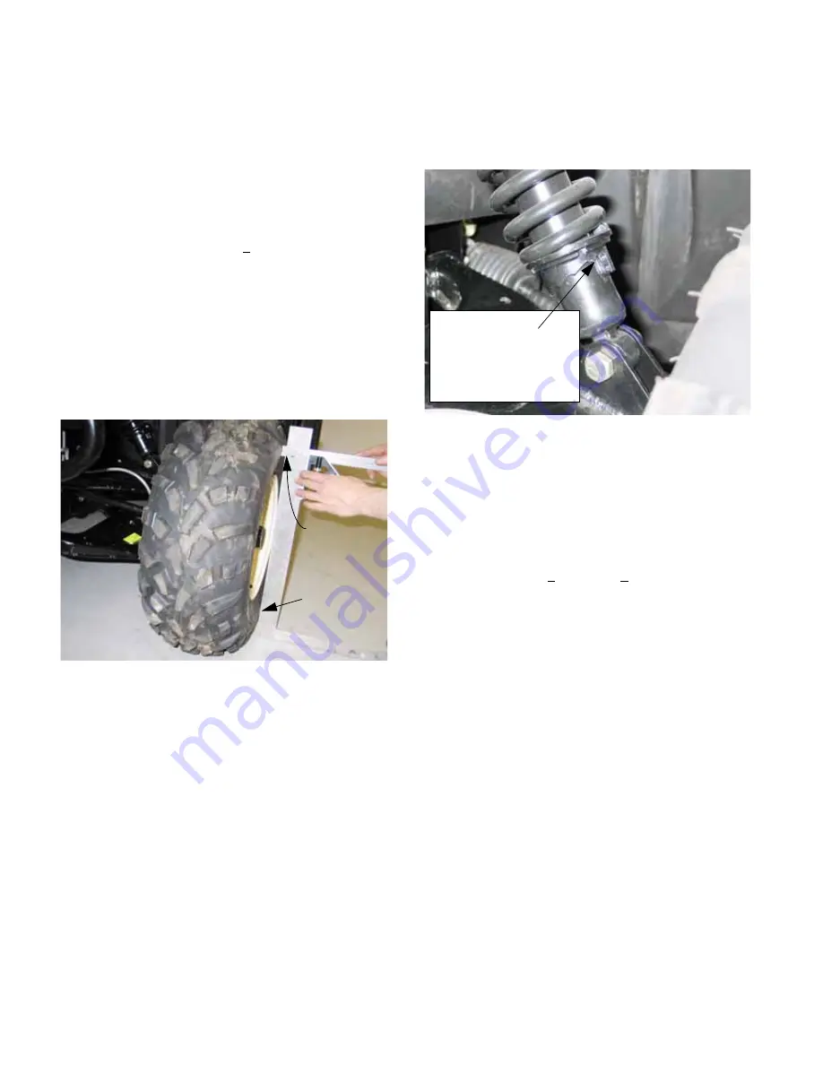
Position the framer’s square vertical against a
plain area on the sidewall of the tire. It should
touch the lower part of the sidewall, but there
should be a gap between the framer’s square
and the upper part of the sidewall.
5.
Measure the distance between the framer’s
square and the nearest spot on the upper side-
wall using the adjustable square.
6.
Camber should be 1.25 + .25 deg. negative:
See Figure 4.14.
•
3/8” (95mm) distance between the framer’s
square and the upper sidewall indicates 1.5
degrees of negative camber.
•
Each 1/16” (1.6mm) is equivalent to .25 degrees
at a height of 21.5” (54.6cm).
•
With the vehicle empty and the tires properly
inflated, tire bulge is negligible.
Adjust the front spring tension to adjust the cam-
ber angle using the factory tool
Part# 759-04125 or a strap wrench.
See Figure 4.15.
•
The front spring tension can be adjusted using a
purpose-made spanner.
•
The front spring tension may be increased to suit
heavier operator(s) or rugged terrain.
•
When the camber is correct, ride height, mea-
sured at the front bottom corner of the frame
should be 10” + 1/2” (25.4 + 1.25cm).
•
Minor adjustments can be made to the front
spring rate and resultant ride height using a pur-
pose-built spanner to rotate the stepped lower
spring perch.
•
If the ride height has fallen beyond the range of
adjustment on one side or both sides, replace
the spring and damper units as a pair.
Effects of camber angle:
•
More negative camber will increase the grip that
the front wheels have when turning the vehicle.
•
Less negative camber will decrease the amount
of grip the front wheels have, but will also
decrease the effective scrub radius slightly,
reducing the amount of force necessary to turn
the steering wheel.
•
Because the engineers have done an excep-
tional job of minimizing “bump steer” in the front
suspension geometry, changes in camber have
minimal effect on toe angle. There is no facility
for camber adjustment at the control arm mount-
ing points nor at the ball joints.
Figure 4.14
Touching
sidewall
3/8” gap
Figure 4.15
camber
tension, ride height, and
steps. This sets spring
position it on different
spring perch to
Rotate the bottom
Содержание Volunteer 4x4 Utility Vehicle
Страница 2: ......
Страница 4: ......
Страница 12: ...Chapter 1 Introduction 8 ...
Страница 66: ...Chapter 2 Drive System CVT and Transfer Case 62 ...
Страница 78: ...Kohler Enclosed CVT Addendum 74 ...
Страница 92: ...Caterpillar Enclosed CVT Addendum 88 ...
Страница 126: ...Chapter 3 Drive System Drive Shafts and Differentials 122 ...
Страница 278: ...Chapter 8 Caterpillar Engine and Related Systems 274 ...
Страница 318: ...Chapter 9 Electrical 314 Electrical Schematic Main Wiring Harness w Kohler engine 725 04351 725 04365 ...
Страница 319: ...Chapter 9 Electrical 315 Electrical Schematic Engine Harness w Kohler engine ...
Страница 320: ...Chapter 9 Electrical 316 Electrical Schematic Main Harness w Caterpillar engine 725 04327 725 04365 ...
Страница 321: ...Chapter 9 Electrical 317 Electrical Schematic Engine Harness w Caterpillar engine 725 04341 ...
Страница 322: ...Chapter 9 Electrical 318 ...
Страница 323: ...1 Front Drive System Differential Gearcase P N 6203 01 280 Parts and Service Manual Rev 0 Released 1 16 2012 ...
Страница 327: ...5 ...
Страница 328: ...6 ...