


Chapter 3 - Drive System: Drive Shafts and Differentials
108
13.
When driving through a curve:
13a. The wheel to the inside of the curve will
rotate the fastest, clamping the rollers
tightest between the inside drive spool
and the ring gear drum.
13b. As the outside wheel tries to slow-down
relative to the inside wheel, the rollers will
move toward the deep center of their
grooves.
13c. As the rollers un-clamp, they allow the
outside wheel to rotate freely, allowing
some differential action.
14.
When in over-run:
14a. When the vehicle is
going down-hill
with
the full traction and front differential
engaged, it will operate as it does on level
ground.
14b. When the vehicle is
decelerating
from the
high end of its operating speed range with
full traction and the front differential
engaged, it will operate as it does in
steady-state motion or acceleration.
14c. If rear wheel traction is lost in over-run
state (either a down-hill or deccelerating)
the front wheels will begin to rotate faster
than the rest of the drive system.
14d. As the front wheels out-run the rest of the
drive system, they may disengage for a
split-second as the rollers shift from the
ramps on the drive side of their grooves to
the ramps on the over-run side of their
grooves.
14e. Few operators will encounter this condi-
tion. Of those that do, only the most per-
ceptive will even notice it.
14f. If the brakes are applied, or the engine
has fallen to idle speed, the condition will
be negated by the brakes and/or the dis-
engagement of the CVT.
REAR DRIVE SHAFT REMOVAL
NOTE:
If the universal joints exhibit enough play
to indicate that they are worn, or if the rear drive-
shaft is identified as the source of a driveline
vibration, replace the driveshaft as an assembly.
NOTE:
Both driveshafts are constantly engaged.
To identify vibration in one drive shaft, the other
must be disconnected. If the vibration goes
away when the shaft is disconnected, it is the
most likely source of the vibration.
1.
Preparation:
1a. Lift and safely support the vehicle to pro-
vide easier access to the bottom of the
front differential.
NOTE:
This procedure can be done on the
ground, but it is easier with the vehicle sus-
pended.
1b. Tilt the cargo box for access to the top of
the differential.
1c. Allow the engine and exhaust system to
cool to a safe temperature before starting
any work in close proximity to them.
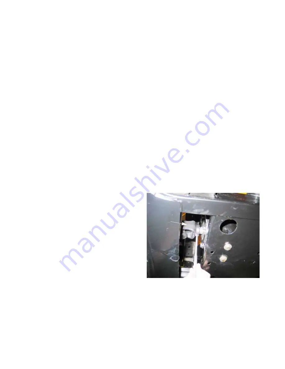
2.
Drive the tension pin out of the joint using 1/4”
flat-nosed drift. See Figure 3.52.
NOTE:
Dispose of the tension pin, and replace it
with a fresh 5/16” X 1-1/4” tension pin.
Figure 3.52
Rear
universal
joint
Содержание Volunteer 4x4 Utility Vehicle
Страница 2: ......
Страница 4: ......
Страница 12: ...Chapter 1 Introduction 8 ...
Страница 66: ...Chapter 2 Drive System CVT and Transfer Case 62 ...
Страница 78: ...Kohler Enclosed CVT Addendum 74 ...
Страница 92: ...Caterpillar Enclosed CVT Addendum 88 ...
Страница 126: ...Chapter 3 Drive System Drive Shafts and Differentials 122 ...
Страница 278: ...Chapter 8 Caterpillar Engine and Related Systems 274 ...
Страница 318: ...Chapter 9 Electrical 314 Electrical Schematic Main Wiring Harness w Kohler engine 725 04351 725 04365 ...
Страница 319: ...Chapter 9 Electrical 315 Electrical Schematic Engine Harness w Kohler engine ...
Страница 320: ...Chapter 9 Electrical 316 Electrical Schematic Main Harness w Caterpillar engine 725 04327 725 04365 ...
Страница 321: ...Chapter 9 Electrical 317 Electrical Schematic Engine Harness w Caterpillar engine 725 04341 ...
Страница 322: ...Chapter 9 Electrical 318 ...
Страница 323: ...1 Front Drive System Differential Gearcase P N 6203 01 280 Parts and Service Manual Rev 0 Released 1 16 2012 ...
Страница 327: ...5 ...
Страница 328: ...6 ...